|
1900-1909 |
1910-1919 |
1920-1924 |
1925-1929 |
1930-1934 |
1935-1939 |
1945-1949 |
1950-1954 |
1955-1959 |
|
|
|
|
|
|
|
|
|
|
|
|
|
1960 |
1961 |
1962 |
1963 |
1964 |
1965 |
1967 |
1969 |
||
|
|
|
|
|
|
|
|
|
|
|
|
1970 |
1971 |
1972 |
1973 |
1974 |
1975 |
1977 |
1979 |
||
|
|
|
|
|
|
|||||
|
1980 |
1981 |
1982 |
1983 |
1984 |
1985 |
1987 |
1989 |
||
|
|
|
|
|
||||||
|
1990 |
1991 |
1992 |
1993 |
1994 |
1995 |
1997 |
1999 |
||
|
|
|
|
|
|
|
||||
|
2000 |
2001 |
2002 |
2003 |
2004 |
2005 |
2007 |
2009 |
||
|
|
|
|
|
|
|||||
|
2010 |
|
|
|
|
|
|
|
|
|
|
|
|
|
|
|
|
|
|
|
|
|
Patent number |
Title of the
patent |
Publication
date |
Inventor
(s) |
Documents cited by the inventor (s) |
Cited documents in search report |
Other patents where this patent is cited in
search report |
Field of
application |
|
Apparatus for shifting the center of gravity of a
vehicle having three wheels or more |
2007-11-08 |
Je-Woo Yu |
None |
KR960017360U KR960017431 US4717164 (human powered) |
None |
1F1T |
|
|
Figure |
Abstract |
||||||
|
|
Disclosed is an apparatus for shifting the center of
gravity of a vehicle having three wheels or more, which includes: a fixed
chassis part on which at least one fixed rail part shaped like a circular arc
having its origin at one point on a virtual line obtained by projecting the
vertical center line of the vehicle body on the ground is included; a movable
chassis part in which at least one movable rail part movably assembled in the
left/right direction relative to the vertical direction of the vehicle body
along the fixed rail part is included; and a control unit for shifting the
center of gravity of the vehicle body so as to shift the center of gravity of
the vehicle body as needed by controlling a shift of the movable rail part of
the movable chassis part relative to the fixed rail part of the fixed chassis
part. According to the apparatus for shifting the center of gravity of a
vehicle having three wheels or more requiring the shifting of the center of
gravity to the left/right relative to the driving direction, upon driving of
the vehicle, the center of gravity is shifted and restored more easily,
effectively, and precisely, and upon stopping, the left/right movement is
precisely controlled. In addition, the apparatus can prevent a tire thereof
from wearing and secure safe driving. |
||||||
|
Patent number |
Title of
the patent |
Publication
date |
Inventor
(s) |
Documents cited by the inventor (s) |
Cited documents in search report |
Other patents where this patent is cited in
search report |
Field of
application |
|
Apparatus for shifting the center of gravity of a
vehicle having three wheels or more and a lozenge-shaped automobile having
the same |
2007-10-25 |
Je-Woo Yu |
None |
US4717164 (human powered) EP1142779 (see Miscellaneous) |
None |
1F1T; Miscellaneous |
|
|
Figure |
Abstract |
||||||
|
|
An apparatus for shifting the center of gravity for
use in a vehicle having three wheels or more, and a lozenge- shaped
automobile having the same are provided. The apparatus comprises a stationary
chassis, a movable chassis, and a gear device for moving the movable chassis
relative to the stationary chassis. The stationary chassis is disposed
perpendicular to the forward direction of the automobile, and has a
stationary rail. The stationary rail is formed in a circular shape having, as
the origin, a point on the line projected on the ground from the longitudinal
center line of the car body parallel to the forward direction of the
automobile. The movable chassis is disposed parallelto the forward direction
of the automobile, and has a moving rail engaged with the stationary rail so
as to move therealong. The moving rail moves to the left/right relative to
the forward direction along the stationary rail. A moving gear is installed
on the movable chassis parallel to the moving rail. A rotating gear is
installed on the stationary chassis so as to be engaged with the moving gear.
A ball screw device is installed so as to be engaged with the rotating gear.
The lozenge- shaped automobile having the above construction includes a
steering unit for simultaneously steering three front wheels in the forward
direction of the automobile. |
||||||
|
Patent number |
Title of
the patent |
Publication
date |
Inventor
(s) |
Documents cited by the inventor (s) |
Cited documents in search report |
Other patents where this patent is cited in
search report |
Field of
application |
|
Dispositif with an articulation locking mechanism |
2006-08-02 |
Pierre Patin Pierre-Armand Patin |
FR2600612 FR2639016 FR2688465 GB1561253 DE3611417 US4223795 |
FR2600612 FR2639016 FR2688465 GB1561253 DE3611417 US4223795 |
None |
1F1T |
|
|
Figure |
Abstract |
||||||
|
|
The vehicle, having two rear wheels (13) and a
single front wheel (22) on two frames (1, 2) with an articulated joint
between them, has a foot-operated mechanism (5) to release the articulated joint
lock (6), especially when the vehicle is in motion, allowing the front frame
to be inclined relative to the vertical and rotated relative to the rear
frame. The mechanism comprises an auxiliary platform fixed to the rear frame
(1), having a foot rest (52) on either side of the central lengthwise axis of
the joint, which is in the form of a shaft on one frame engaging with a bush
on the other. |
||||||
|
Patent number |
Title of
the patent |
Publication
date |
Inventor
(s) |
Documents cited by the inventor (s) |
Cited documents in search report |
Other patents where this patent is cited in
search report |
Field of
application |
|
Tilting Vehicle provided with a moment-compensating
device |
2006-01-19 |
Hendrik Kroonen Christopher Van Den Brink |
WO2004011324
(see 2F3T) US4088199 (see 2F3T) |
US6435522 (see WO9924308) US6328125 (see WO9914099) |
None |
1F1T |
|
|
Figure |
Abstract |
||||||
|
|
Tilting vehicle provided with a first frame section and
a second frame section, joined to one another such that they can tilt about a
tilt axis located in the longitudinal direction, wherein each frame section
is provided with at least one wheel, wherein the first frame section has a
driver's seat.; The first frame section has a drive device with a rotary
drive shaft, which is connected via a mechanical coupling to a wheel axle of
the at least one wheel of the second frame section, wherein the tilting
vehicle is provided with a moment sensor which is coupled to the drive shaft
for determining a moment exerted by the drive shaft, and a force generator
that, at one end, is mechanically connected to the first frame section and,
at the other end, is mechanically connected to the second frame section and
that is coupled to the moment sensor for exerting a moment between the first
frame section and the second frame section depending on the moment of the
drive shaft determined by the moment sensor. |
||||||
|
Patent number |
Title of
the patent |
Publication
date |
Inventor
(s) |
Documents cited by the inventor (s) |
Cited documents in search report |
Other patents where this patent is cited in
search report |
Field of
application |
|
Three-wheel motor vehicle and method for the
operation thereof |
2005-12-22 |
Bernhard Niedermayr |
None |
US6062581 (human powered) GB556451 (irrelevant) US6247714 (human powered) US6435522 FR1521625 (irrelevant) US5518081 (irrelevant) US4412595 (irrelevant) FR2834683 (irrelevant) |
None |
1F1T |
|
|
Figure |
Abstract |
||||||
|
|
The invention relates to a three-wheel motor vehicle
(1) comprising a rear axle (7) with two rear wheels (H) as well as a frame (2)
which is connected to the rear axle (7) by means of a tilting technique (20)
and is provided with a single steerable front wheel (V) on a front wheel fork
(21). Steering mechanisms (22) whose actuators (23) are accessible at least
substantially below and/or next to a driver's (4) seat (3) which is
associated with the frame (2), are provided for steering the front wheel (V).
The invention further relates to a method for operating a three-wheel motor
vehicle (1), according to which a driver (4) actuates actuators (23) of
steering mechanisms (22) to steer a single front wheel (V) of the three-wheel
motor vehicle (1) comprising a frame (2), said actuators (23) being
accessible below and/or next to a seat (3) associated with the frame (2). |
||||||
|
Patent number |
Title of
the patent |
Publication
date |
Inventor
(s) |
Documents cited by the inventor (s) |
Cited documents in search report |
Other patents where this patent is cited in
search report |
Field of
application |
|
A three wheeled vehicle with tilting mechanism |
2005-04-07 |
James Dower |
US4572535 (human
powered) US5927424 (see WO9534459) |
EP0592377 (see 2F4T) US5678835 (human powered) |
EP1561612 (see 2F3T) |
1F1T |
|
|
Figure |
Abstract |
||||||
|
|
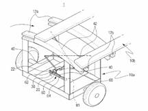
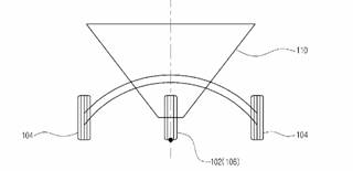
A three wheeled vehicle (1) having a front section
(10) and a rear section (11). The front section (10) comprises a front frame
(105), a directionally controllable front wheel (101) and a steering column
(104) with a handlebar (1040) for controlling the front wheel (101). The rear
section (11) comprises a rear frame (107) and two rear wheels (102,103). The
front section (10) of the vehicle is pivotable with respect to the rear
section (11) about a pivot axis (111) located intermediate the two rear
wheels (102,103). The pivot axis (111) extends from the rear section (11)
towards front section (10). The pivot axis (111) is provided by a pivot means
comprising a pivot bar (401) and a pivot bar housing (402) arranged between
the front section (10) and the rear section (11).; The pivot means are in
communication with a transmission mechanism comprising a first gear pair (2)
and a second gear pair (3). The transmission mechanism is releasably
connected to the steering column (104) and is capable of pivoting the first
section (10) about the pivot axis (111) towards the centre of the curvature
of the turn in accordance with the angle of turn of the front wheel (101),
thus providing greater stability for the vehicle (1) during a turn while the
rear section (11) remains in an unchanged position. |
||||||
|
Patent number |
Title of
the patent |
Publication
date |
Inventor
(s) |
Documents cited by the inventor (s) |
Cited documents in search report |
Other patents where this patent is cited in
search report |
Field of application |
|
Roll control device for rolling type vehicle |
2005-03-23 |
Yoshihisa Ieda Akihiko Tomoda Shinji Takayanagi |
None |
EP0004230 US3601213 EP0369863 |
None |
1F1T |
|
|
Figure |
Abstract |
||||||
|
|
A roll control device for a motorized three-wheeled vehicle
(10) in which a vehicle body rolls, is characterized in that the angle of
force acting on either a vehicle body (16) side which is a rolling side
vehicle body or suspension arms (71, 72) side which is a non-rolling side
vehicle body is detected, and, based on the detected angle, the relative roll
angle between the vehicle body (16) side and the suspension arms (71, 72)
side is controlled. |
||||||

|
Patent number |
Title of
the patent |
Publication
date |
Inventor
(s) |
Documents cited by the inventor (s) |
Cited documents in search report |
Other patents where this patent is cited in
search report |
Field of
application |
|
Suspension
arrangement structure for vehicle |
2004-11-18 |
Masahiro Kuroki Shinji Takayanagi |
None |
None |
None |
1F1T |
|
|
Figure |
Abstract |
||||||
|
|
A differential mechanism is arranged below an
infinitely variable transmission and a reduction gear mechanism. Front fitting
parts and rear fitting parts for fitting suspension arms to a vehicle frame
are arranged to the front and rear of the deferential mechanism. Even though
the left and right suspension arms swing up and down, or a transmission and a
reduction gear mechanism attached on a vehicle frame swing left and right
with respect to the suspension arms, there is no interference of the
transmission and the reduction gear mechanism with the suspension arms due to
a space at the front and the rear of a differential mechanism, so that the
vehicle frame can swing left and right and it is also possible to easily
constitute a vehicle having an independent suspension. |
||||||
|
Patent number |
Title of
the patent |
Publication
date |
Inventor
(s) |
Documents cited by the inventor (s) |
Cited documents in search report |
Other patents where this patent is cited in
search report |
Field of
application |
|
Tilt trike |
2004-05-05 |
Mills Stuart |
US04065144 (see 1F3T) US4624469 (see 2F3T) US4132435 US4360224 (see 2F3T) US4088199 (see 2F3T) US5927242 (irrelevant) WO8702951 (see 2F3T) |
JP1016856 US4065144 (see 1F3T) US6328125 (see WO9914099) |
None |
1F1T |
|
|
Figure |
Abstract |
||||||
|
|
A three wheeled vehicle comprises a two wheeled rear
frame carrying an engine and transmission and a front frame pivotably connected
at two points to the rear frame whereby a steerable front wheel is tilted and
whereto a seat is mounted. The vehicle negotiates corners by a combination of
front wheel tilting and steering. The pivots are preferably aligned with each
other and with the front wheel road contact point. The rearward pivot is
behind and above the seat, which may be inside an enclosure. Foot pedals
allow a driver to mechanically control tilting and righting of the front
frame. Centring of the tilt mechanism may also be assisted by the inertia of
the driver's body and by a spring and damper on left and right sides. Rear
shock absorption is also provided. The trike is sufficiently stable to be
capable of travelling in a straight line even when the front frame is tilted to
one side. |
||||||
|
Patent number |
Title of
the patent |
Publication
date |
Inventor
(s) |
Documents cited by the inventor (s) |
Cited documents in search report |
Other patents where this patent is cited in
search report |
Field of
application |
|
Three-wheeled vehicle provided with swinging
mechanism |
2004-03-31 |
Shinji Takayanagi Yohei Makuta |
None |
US4974863 (see 1F3T) DE29705386U US6250649 (see 2F3T; WO9849023) FR2689082 (human powered) |
1F1T |
||
|
Figure |
Abstract |
||||||
|
|
Not available |
||||||
|
Patent number |
Title of
the patent |
Publication
date |
Inventor
(s) |
Documents cited by the inventor (s) |
Cited documents in search report |
Other patents where this patent is cited in
search report |
Field of
application |
|
Three-wheeled vehicle provided with swinging
mechanism |
2004-03-31 |
Shinji Takayanagi Yohei Makuta Hiroyoshi Kobayashi |
None |
US4546997 (see 2F3T) JP55110680 (See US4316520) |
None |
1F1T |
|
|
Figure |
Abstract |
||||||
|
|
In a
three-wheel vehicle, right and left suspension arms are independently
attached to a front swinging shaft and a rear swinging shaft so that the
suspension arms can swing vertically, and the front swinging shaft and the
rear swinging shaft function as a swinging shaft for swinging the body frame.
A swinging mechanism is provided to restrict lateral rotation of the body
frame. |
||||||
|
Patent number |
Title of the
patent |
Publication
date |
Inventor
(s) |
Documents cited by the inventor (s) |
Cited documents in search report |
Other patents where this patent is cited in
search report |
Field of
application |
|
Dispositif de
solidarisation entre deux parties d�une articulation, en particulier pour un
v�hicule |
2003-12-26 |
Pierre Patin |
FR2600612 (see 1F3T EP0251906) FR2639016 (see 1F3T US4974863) FR2688465 (see 1F3T US5437467) GB1561253 (see 2F3T) |
FR2688465 (see 1F3T US5437467) FR2639016 (see 1F3T US4974863) GB1561253 (see 2F3T) |
None |
1F1T |
|
|
Figure |
Abstract |
||||||
|
|
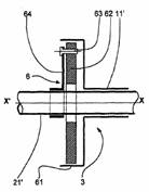
L'invention
a pour objet un dispositif de solidarisation entre deux parties articul�es
l'une sur l'autre autour d'un axe longitudinal, comprenant deux pi�ces
solidaires en rotation, respectivement, de chacune des deux parties
articul�es, respectivement une virole (61) centr�e sur l'axe longitudinal
d'articulation (x'x) et un bras (64) de suspension d'un organe pendulaire de
blocage (62) ayant une face inf�rieure (66) �cart�e par un faible jeu (j) de
la face interne de la virole (61) de fa�on � prendre appui sur celle-ci avec
arc-boutement, en cas de d�viation angulaire excessive du bras de suspension
(64) par rapport � la direction de la verticale apparente. L'invention
s'applique sp�cialement aux v�hicules � trois roues inclinables par rapport
au sol. |
||||||

|
Patent number |
Title of
the patent |
Publication
date |
Inventor
(s) |
Documents cited by the inventor (s) |
Cited documents in search report |
Other patents where this patent is cited in
search report |
Field of
application |
|
Vehicle with a stabilized tilting section |
2003-06-05 |
Eric Saqueton Bautista |
US4088199 US4351410 US4624469 US5927424 US4072325 |
None |
WO2010001397 WO2009069170 WO2007093579 EP1630081 (see 2F3T) |
1F1T; 2F1T |
|
|
Figure |
Abstract |
||||||
|
|
In accordance with the present invention a vehicle comprises
a tilting section and a hanging section both connected to each other. When
the vehicle is stationary or traveling straight, gravity will pull the
hanging section downwards which will stabilize and keep the tilting section
upright. When the vehicle is turning, centrifugal force will swing the
hanging section outward and tilt the tilting section inside the turn. |
||||||
|
Patent number |
Title of
the patent |
Publication
date |
Inventor
(s) |
Documents cited by the inventor (s) |
Cited documents in search report |
Other patents where this patent is cited in
search report |
Field of
application |
|
|
Three wheeled motorbike has chassis pivoted in two
parts relative to pivot pin located in rear of vehicle |
2003-05-09 |
Michel Arias |
None |
WO0102235 (irrelevant) US4432561 (human powered) |
FR2872772 (see 2F4T) |
1F1T |
|
Figure |
Abstract |
||||||
|
|
The motorbike has a chassis pivoting in two parts
(1,2) relative to a pivot pin (3). The pivot pin is placed in the rear of the
vehicle high enough and with a degree of inclination so that when the driver
(4) during running is projected in the pivot pin axis (21) he is below this
axis. |
||||||
|
Patent number |
Title of
the patent |
Publication
date |
Inventor
(s) |
Documents cited by the inventor (s) |
Cited documents in search report |
Other patents where this patent is cited in
search report |
Field of
application |
|
WO02098722 |
Articulated three-wheeled vehicle has front and rear
frames connected by articulated joint with foot-controlled lock and release
mechanism |
2002-12-13 |
Pierre Patin |
FR2600612 (see 1F3T EP0251906) FR2639016 (see 1F3T US4974863) FR2688465 (see 1F3T
US5437467) |
FR2688465 (see 1F3T US5437467) FR2639016 (see 1F3T US4974863) GB1561253 (see 2F3T) |
1F1T |
|
|
Figure |
Abstract |
||||||
|
|
The vehicle, having two rear wheels (13) and a
single front wheel (22) on two frames (1, 2) with an articulated joint
between them, has a foot-operated mechanism (5) to release the articulated
joint lock (6), especially when the vehicle is in motion, allowing the front
frame to be inclined relative to the vertical and rotated relative to the
rear frame. The mechanism comprises an auxiliary platform fixed to the rear
frame (1), having a foot rest (52) on either side of the central lengthwise
axis of the joint, which is in the form of a shaft on one frame engaging with
a bush on the other. |
||||||
|
Patent number |
Title of
the patent |
Publication
date |
Inventor
(s) |
Documents cited by the inventor (s) |
Cited documents in search report |
Other patents where this patent is cited in
search report |
Field of
application |
|
Vehicle body structure of tricycle |
2002-03-07 |
Takuya Tagami Takashi Ozeki Mitsuo Nakagawa |
None |
None |
1F1T |
||
|
Figure |
Abstract |
||||||
|
|
A joint case includes a flange, a joint shaft extending
from the flange, and a case main body fitted to the joint shaft. The flange
is fitted to a rear portion of a front vehicle body, whereas the side of the
case main body of the joint case is fitted to a rear vehicle body. With the
above construction of the joint case, the distance between the front vehicle
body and the rear vehicle body can be reduced, and a reduction in the overall
length of the tricycle can be obtained. |
||||||

|
Patent number |
Title of
the patent |
Publication
date |
Inventor (s) |
Documents cited by the inventor (s) |
Cited documents in search report |
Other patents where this patent is cited in
search report |
Field of
application |
|
Tilting vehicle provided with steerable rear wheels |
2001-11-22 |
Hendrik Kroonen Christopher Van Den Brink |
EP0878378 (irrelevant) |
GB2394453 (irrelevant) FR2839937 (irrelevant) |
1F1T |
||
|
Figure |
Abstract |
||||||
|
|
The invention relates to a tilting vehicle (1) with
a front frame section (2) having a longitudinal axis (8), a driver's seat (7)
and one or more wheels (4) that are able to turn about a front wheel steering
axis (5) located transversely to the longitudinal axis (8). The vehicle has a
rear frame section (3) with two wheels (14, 15) that is connected to the
front frame section (2) such that it can tilt. The vehicle can also be
provided with a tilting device (9), that can be operated by the driver, for
relative tilting of the front and rear frame sections (2, 3). A sensor (12)
measures, for example, a force or a movement on the front wheel (4) for
controlling the tilting device (9).; The rear wheels (14, 15) of the rear
frame section (3) can be turned about a rear wheel steering axis (19, 20)
located transversely to the longitudinal axis or can be tilted about a rear
wheel tilt axis (17, 18) located essentially in the direction of the
longitudinal axis (8) in order to prevent oscillations of the vehicle (1) at
relatively high speeds. |
||||||
|
Patent number |
Title of
the patent |
Publication
date |
Inventor
(s) |
Documents cited by the inventor (s) |
Cited documents in search report |
Other patents where this patent is cited in
search report |
Field of
application |
|
Mechanism for the construction of a three-wheeled
vehicle with front rolling part |
2001-01-24 |
Vittore Cossalter |
None |
FR2522590 (see 1F3T) EP0606191 (see 1F3T) FR2680348 (see 1F3T) |
None |
1F1T |
|
|
Figure |
Abstract |
||||||
|
|
Mechanism for the construction of a three-wheeled vehicle
with front rolling part (1). The front part of the vehicle is linked to the
rear part (8) by a four-sided mechanism. During movement on a bend it is
inclined as normally takes place in two-wheeled vehicles, and the rear part
is not involved in the rolling movement. The mechanism is made up of four
members: one member known as the front frame (2) is connected to the front
rolling part of the vehicle, a second member known as the rear frame (5) is
connected to the non-rolling part of the vehicle, and the other two members
(3,4) that link the two frames determine the position of the roll axis (y) of
the front member with respect to the rear. The plane (v) on which the
mechanism is positioned is perpendicular to the longitudinal plane of the
vehicle. Variants will be produced. |
||||||
|
Patent number |
Title of
the patent |
Publication
date |
Inventor
(s) |
Documents cited by the inventor (s) |
Cited documents in search report |
Other patents where this patent is cited in
search report |
Field of application |
|
Tilting vehicle |
1999-05-20 |
Hendrik Kroonen Christopher Van Den Brink |
EP0592377 (see 2F4T) EP0020835 (see US4484648) |
None |
1F1T |
||
|
Figure |
Abstract |
||||||
|
|
The invention relates to a vehicle (1) provided with
a frame having two frame sections (3, 4) which are able to tilt with respect
to one another. An opposite lock power transmitter (50) is connected to a
steerable front wheel (13). The opposite lock power transmitter (50) is
controlled as a function of the tilting moment on the frame sections (3, 4).
By this means application of opposite lock is achieved, as a result of which
the tilting section of the vehicles "drops into the bend" more
rapidly and as a result of which increased manoeuvrability is obtained. The
opposite lock power transmitter (50) can be used on vehicles having an active
tilting system with drive means, such as, for example, hydraulic tilting
cylinders (9, 9'), which are controlled by a sensor depending on the radius
of the bend (24).; The tilting moment generated by the tilting cylinders (9,
9') can optionally serve as a control signal for the opposite lock power
transmitter (50). As a result of the active application of opposite lock, the
tilting cylinders (9, 9') can be of relatively small construction. |
||||||
|
Patent number |
Title of
the patent |
Publication
date |
Inventor
(s) |
Documents cited by the inventor (s) |
Cited documents in search report |
Other patents where this patent is cited in
search report |
Field of
application |
|
Tilting vehicle |
1999-03-25 |
Hendrik Kroonen Christopher Van Den Brink |
EP0592377 (see 2F4T) EP0020835 (see US4484648 ) |
AU2002233045 (irrelevant) WO2006130007 (see 1F3T) |
1F1T |
||
|
Figure |
Abstract |
||||||
|
|
The invention relates to a vehicle (1) provided with
a frame (2) having a front frame part (3) and a rear frame part (4) which can
tilt with respect to one another. The vehicle (1) comprises three or more
wheels (7, 7', 13), it being possible to rotate the front wheel (13) with
respect to the steering column (18). In this case, a sensor (24) determines
the angle of rotation between the front wheel (13) and the steering column
(18) and, as a function of this angle of rotation, actuates the tilting means
(9, 9') of the vehicle. As a result of the consequent tilting of the front
frame part (3) and as a consequence of the speed at which the vehicle (1) is
travelling, the front wheel (13) and the tilting angle will automatically
adopt the correct level for allowing the vehicle (1) to travel through the
bend in a stable manner at the given speed.; Controlling the tilt via the
difference in angular rotation between the steering column (18), which is
flexibly connected to the front wheel (13), and the front wheel (13), it is
possible to control the tilt in a simple and robust manner. |
||||||
|
Patent number |
Title of
the patent |
Publication
date |
Inventor
(s) |
Documents cited by the inventor (s) |
Cited documents in search report |
Other patents where this patent is cited in
search report |
Field of
application |
|
Swing small-sized three-wheeled vehicle |
1999-01-19 |
Isao Murakami |
? |
None |
1F1T |
||
|
Figure |
Abstract |
||||||
|
|
PROBLEM TO BE SOLVED: To provide a swing small-sized
three-wheeled vehicle wherein without spreading width of a body, running
stability is maintained, even at the rainfall time or the like, so as to
prevent an influence from being given to drive operation, and as necessary, a
car body attitude is stabilized at a low speed time and a stopping time.
SOLUTION: A vehicle comprises a drive unit having two rear wheels, chassis
unit having a single front wheel and a handle to be able to tilt in a
right/left direction relating to the drive unit, seat mounting unit mounted
in the chassis unit to be able to right/left swing with a front up swing
center axis 100 serving as the center, a seat mounted in the seat mounting
unit, and a body. The vehicle has an auxiliary wheel 18 grounded by lowering
down operation. |
||||||
|
Patent number |
Title of
the patent |
Publication
date |
Inventor
(s) |
Documents cited by the inventor (s) |
Cited documents in search report |
Other patents where this patent is cited in
search report |
Field of
application |
|
Vehicle |
1998-11-03 |
Jan Vanmeerbeek |
EP0251906 (see 1F3T) EP0369863 (see 1F3T
US4974863) EP0592377 (see 2F4T) EP0626307 (see 1F3T) |
NL8403016 DE2553960 EP0282333 (see Miscellaneous) |
FR2872772 (see 2F4T) WO2005120938 |
1F1T |
|
|
Figure |
Abstract |
||||||
|
|
The invention relates to a vehicle, equipped with a
carrying section with a front wheel and a driving section , that freely turns
around a lengthwise axis line in a loaded state from the driver's section
situated above the centre of gravity of it, as a result of which the driver
section will spontaneously assume a slope depending on the turning radius and
speed of the vehicle when executing a turn. The vehicle is consequently
extremely stable. In addition the driver's section can contain a wheel that
can be steered and the axis over a contact point of this wheel is situated
with a base, which further increases the turning stability of the vehicle in
bends. |
||||||
|
Patent number |
Title of
the patent |
Publication
date |
Inventor
(s) |
Documents cited by the inventor (s) |
Cited documents in search report |
Other patents where this patent is cited in
search report |
Field of
application |
|
Device for restricting the inclination of a motor
vehicle |
1998-08-31 |
Georgi Chervendinev |
? |
None |
None |
1F1T |
|
|
Figure |
Abstract |
||||||
|
|
The device is used in three- and four-wheel motor
vehicleswith inclination at the bends or along an inclined surface.
Itprevents overturning in all modes of running and at rest of themotor vehicle
and improves the comfort in running on terrainshaving changing side
inclinations. The device consists of ahousing fixed to a two-wheel bridge,
and an internal part housedinside the housing (1) and fixed to the frame (5)
of the motorvehicle. Housing (1) is a cylindrical body with externally
coggedsurface in the form of a gear rim (11), and its internal part asan axle
(2). Axle (2) is fitted at end upper position of thehousing (1) close to the
gear rim (11), and to it a pendulum (5)is hung fabricated as a symmetrical
eliptical body having at leasttwo gear sectors (31, 32) fitted symmetrically
towards itsvertical axis of symmetry. |
||||||
|
Patent number |
Title of
the patent |
Publication
date |
Inventor
(s) |
Documents cited by the inventor (s) |
Cited documents in search report |
Other patents where this patent is cited in
search report |
Field of
application |
|
Three-wheel motor
vehicle |
1998-06-11 |
Kurt Aregger |
None |
EP0529188 (irrelevant) GB2074957 (see US4325565) |
WO2007112118 (irrelevant) |
1F1T
|
|
|
Figure |
Abstract |
||||||
|
|
The three-wheel motor vehicle consists of two parts
(10,2) which can pivot around the longitudinal axis. The rear part (2) has a
chassis for double-tracked wheels (6), whereas the front part (1), which
pivots with relation to this rear part (2), bears the driver's seat (22).
Coupled to the front end of the front motor vehicle part (1) is a pivoting
front-wheel suspension, to which are attached not only the front wheel (7),
but also the motor (8) with the gearing (9) for the front-wheel drive. Both
motor vehicle parts (1,2), which pivot in relation to each other, each hold
or form a car body (44, 52), which can also be executed as a monocoque for
the front part (1), and a closed, heated driver's cabin (45). |
||||||

|
Patent number |
Title of
the patent |
Publication
date |
Inventor
(s) |
Documents cited by the inventor (s) |
Cited documents in search report |
Other patents where this patent is cited in
search report |
Field of
application |
|
Self-stabilising, directionally controllable vehicle
with at least three wheels |
1995-12-21 |
Hendrik Kroonen Anthonie Van Den Brink Christopher Van Den
Brink |
GB2225990 (irrelevant) |
EP0592377 (see 2F4T) EP0020835 (see US4484648 ) GB2155410 (see
2F3T) EP0163382 (automotive patents) |
WO2006130007 (see 1F3T) WO2005075278 (see 2F3T) CZ20001694 (no detail) |
1F1T |
|
|
Figure |
Abstract |
||||||
|
|
Self-balancing vehicle with at least three wheels
resting on the ground, at least two of which wheels are arranged on either
side of the centre of gravity with respect to the longitudinal axis of the vehicle,
and at least one of which wheels is directionally controllable, and wherein
at least one section of the vehicle is tiltable about the longitudinal axis
of the vehicle and a sensor for measuring the magnitude and/or the direction
of the load, for the purpose of producing and/or maintaining a change in
direction of the directionally controllable wheel during travel, and/or for
measuring the magnitude and/or the direction of a change in direction of the
directionally controllable wheel during travel, is connected to a control
element for controlling the at least one directionally controllable wheel,;
and a power-assisted tilt element is provided for tilting said vehicle
section about the longitudinal axis of the vehicle, which tilt element is
connected to the sensor, in order to produce a tilt as a function of the
registration by the sensor. |
||||||
|
Patent number |
Title of
the patent |
Publication
date |
Inventor
(s) |
Documents cited by the inventor (s) |
Cited documents in search report |
Other patents where this patent is cited in
search report |
Field of
application |
|
Motor tricycle |
1993-06-22 |
Akihiko Muramatsu |
? |
None |
None |
1F1T |
|
|
Figure |
Abstract |
||||||
|
|
PURPOSE:To enhance steering performance and
stability at the time of cornering by making the lean characteristic of a car
body frame laterally uniform at the time of cornering, and concurrently
preventing the reaction of a shock absorber from disturbing the lean of the
car body frame. CONSTITUTION:A car body frame 2 is provided with a first
joint unit 15 located above the plane center line A of a motor tricycle 1,
and with a second joint section 16 located to the side of the first joint
unit 15 while being apart from the unit, the first joint unit 15 is connected
to the front part of a power unit 11, and a third joint unit 21 located on
the plane center line A is provided for the rear part of the power unit 11,
so that the third joint unit 21 is connected to the second joint unit 16 with
a tension rod 22.; The upper end 28a of a shock absorber 28 is connected to
the car body frame 2 while being located on the plane center line A, and its
lower end 28b is connected to the power unit 11 in such a way that the lower
end coincides with a lean axis B passing through the first joint unit 15 and
the third joint unit 21. |
||||||
|
Patent number |
Title of
the patent |
Publication
date |
Inventor
(s) |
Documents cited by the inventor (s) |
Cited documents in search report |
Other patents where this patent is cited in
search report |
Field of
application |
|
Front-frame tilted electric tricycle |
1991-05-09 |
Sadao Tanaka Ikutoshi Nehashi Kiminori Fukuda Fujio Nakajima Masaro Ono Atsushi Mamiya |
� |
None |
WO2008044838 (see 1F3T; 2F3T) US6402174 (human powered) |
1F1T |
|
|
Figure |
Abstract |
||||||
|
|
PURPOSE:To improve comfortability, running stability
and cornering stability by connecting front and rear frames with rolling
allowable by a pivot joint and connecting the stator-side frame of a rear
wheel, formed as a direct-drive system electric wheel, to the rear frame with
crosswise tilting allowable under a cushion spring. CONSTITUTION:A front
frame 2 and a rear frame 3 are connected with rolling allowable by a pivot
joint device. A rear wheel 5 is made up as a direct-drive system electric
wheel in such a manner that the stator and the rotor of an electric motor 8
are incorporated in between a shaft and a disk. Then, a stator frame 6 is
pivotaly supported to the rear frame 3 with crosswise tilting allowable by
front and rear arms 15 which are projected so as to form two sides of a right
triangle as viewed in plane.; It is thus possible to improve comfortability,
running stability and, in special, cornering stability. |
||||||
|
Patent number |
Title of
the patent |
Publication
date |
Inventor
(s) |
Documents cited by the inventor (s) |
Cited documents in search report |
Other patents where this patent is cited in
search report |
Field of
application |
|
Oscillating reversal mechanism of motor tricycle |
1990-09-12 |
Katsuhiro Kato |
? |
None |
None |
1F1T |
|
|
Figure |
Abstract |
||||||
|
|
PURPOSE:To provide restoring force with a large
oscillating angle in vertical or horizontal direction and no movement of an
oscillating fulcrum regardless of a small design of a motor tricycle by
making the relative oscillating amounts of a shaft to the outermost
cylindrical body equal to the sum of all the respective relative oscillating
amounts of the innermost cylindrical body and mutually adjoining cylindrical
bodies. CONSTITUTION:The relative oscillating amount of a shaft 20 to the
outermost cylindrical body 14 becomes the total sum of the relative
oscillating amount of the outermost cylindrical body 14 to a middle
cylindrical body 16, the relative oscillating amount of the middle
cylindrical body 16 to the innermost cylindrical body 18 and the relative
oscillating amount of the innermost cylindrical body 18 to the shaft 20.; As
a result, the shaft 20 and the outermost cylindrical body 14 can be
relatively oscillated against the elastic force of rubbers 22, 24, 26 within
the maximum oscillating range of 30 + 30 + 30 = 90 degree. Moreover, elastic
energy is accumulated by elastic deformation of rubbers 22, 24, 26 due to
relative oscillation, and after rear wheels 9, 9 rides across roughness,
restoring force is generated by the elastic energy. It is thus possible to
provide the optimum restoring force by selecting the material of rubbers 22,
24, 26 and so forth. |
||||||
|
Patent number |
Title of
the patent |
Publication
date |
Inventor
(s) |
Documents cited by the inventor (s) |
Cited documents in search report |
Other patents where this patent is cited in
search report |
Field of
application |
|
Vehicle with roof |
1990-06-21 |
Akio Yagasaki Masaki Watanabe |
? |
None |
None |
1F1T |
|
|
Figure |
Abstract |
||||||
|
|
PURPOSE:To reduce the side projected area of a car
body and reduce the effect of the cross wind by offsetting and arranging a
handle behind a head pipe and inclining a wind screw backward and extending it
above a seat. CONSTITUTION:A wind screen 15 largely inclined obliquely
backward is elected from the front end and both the right and left sides of a
front floor 11 and extended above a seat 34. A handle post cover 21 is
provided on an inclined floor 12 obliquely backward, a front fork and a head
pipe are provided in it, and a steering shaft is inserted. A handle 25 is
connected to the head pipe via an upper stem. The handle 25 is offset and
arranged behind the head pipe and does not interfere with the wind screen 15
inclined backward. The side projected area of a car body is reduced, and the
effect of the cross wind can be reduced. |
||||||
|
Patent number |
Title of
the patent |
Publication
date |
Inventor
(s) |
Documents cited by the inventor (s) |
Cited documents in search report |
Other patents where this patent is cited in
search report |
Field of
application |
|
Parking device for rocking type tricycle |
1989-01-25 |
Hirakado Fujii |
? |
None |
None |
1F1T |
|
|
Figure |
Abstract |
||||||
|
|
PURPOSE: To concurrently lock a junction connecting
a rear body rockably to the right and left and a drive wheel by operating a
parking lever, to operate a steering lock mechanism, and to take these actions
in a single operation. CONSTITUTION: The front body 2 and rear body 7 of a
tricycle are connected via a junction 9 so that the front body 2 can be
rocked to the right and left. A swing lock plate 17 is integrally fixed to
the front end of a rocking shaft 11, hook grooves 18 are provided on the
swing lock plate 17 at five places, a stopper 19 is rotatably fitted to the
end face of the swing lock plate 17, and the hook piece 20 of the stopper 19
is coupled with the hook groove 18 to lock the rocking shaft 11. The stopper
19 is connected to a parking cable 23, and the parking cable 23 is connected
to a drive wheel lock mechanism and a steering lock mechanism. |
||||||
|
Patent number |
Title of
the patent |
Publication
date |
Inventor
(s) |
Documents cited by the inventor (s) |
Cited documents in search report |
Other patents where this patent is cited in
search report |
Field of
application |
|
|
Scooter with two rear wheels swinging in opposite
directions |
1987-10-22 |
Adolf Fichtner |
None |
None |
GB2450740 (see 1F3T) EP1884457 (see 2F4T) WO2007127783 (see 1F3T; 2F3T; 2F4T) WO02098722 (see FR2825672) DE19954999 (see 1F3T) WO9727071 (see 1F3T) FR2755933 (see Miscellaneous) DE19540578 (see WO9716339, 1F3T) ES2104494 (see 1F3T) EP0626307 (see 1F3T) DE4035128 (see 1F3T) |
1F1T 1F3T |
|
Figure |
Abstract |
||||||
|
|
In order to eliminate the risk of the motorcycle
falling over and the three-wheeled vehicle tipping over, the two rear wheels
of the scooter with a cab swing parallel to the plane of symmetry of the vehicle,
the style of driving the motorcycle is preserved, the vehicle enters at an
inclination (optionally up to a stop) into the curve. In the position of
rest, the vehicle is locked against inclination to the side, it behaves,
likewise in first gear, as a three-wheeled vehicle. On changing up to second
and the higher gears the lock is released, the vehicle then behaves as a
motorcycle. When changing down to first gear the lock again comes into
operation, the vehicle can be parked as a three-wheeled vehicle. By means of
two pedals coupled to the rear wheels the driver may at any time also have an
influence on the position of the vehicle. The feet are no longer used for
support on the ground, the vehicle may be provided with any desired
protection against the weather up to the vehicle body being fully closed
(with heating), already tested in 1946 (including two people spending a night
in the vehicle). |
||||||
|
Patent number |
Title of
the patent |
Publication
date |
Inventor
(s) |
Documents cited by the inventor (s) |
Cited documents in search report |
Other patents where this patent is cited in
search report |
Field of
application |
|
Tiltable tricycle |
1987-07-07 |
Masaki Watanabe Hitoshi Yamamoto Yoshinori Matsuoka Kunihiko Tanaka |
US3094187 (irrelevant) US4325449 (irrelevant) US4392536 (irrelevant) |
DE10100562 (irrelevant) US6286619 (irrelevant) US5927424 (see WO9534459) |
1F1T |
||
|
Figure |
Abstract |
||||||
|
|
A tiltable tricycle comprises a body frame, a single
front wheel steerably supported on a front portion of the body frame, a power
unit mounted on a rear portion of the body frame and including at least an
engine, a joint case connected to the power unit for vertical angular
movement, a rear axle support case connected to the joint case for lateral
rolling movement, a rear axle assembly rotatably supported on the rear axle
support case, a pair of rear wheels coupled to the rear axle assembly,
respectively, and a shock absorber disposed between the body frame and the
joint case. |
||||||
|
Patent number |
Title of
the patent |
Publication
date |
Inventor
(s) |
Documents cited by the inventor (s) |
Cited documents in search report |
Other patents where this patent is cited in
search report |
Field of
application |
|
Oscillation control apparatus for oscillation
type vehicle |
1987-05-19 |
Masanori Shibuya |
None |
US4515390 (irrelevant) |
WO9408807 (irrelevant) US5485893 (irrelevant) US5107950 (see Miscellaneous) US5060749 (see Miscellaneous) US5042608 (irrelevant) US4984650 (irrelevant) US4887688 (irrelevant) |
1F1T |
|
|
Figure |
Abstract |
||||||
|
|
An oscillation control apparatus for an oscillation
type vehicle in which a front frame for supporting a front wheel and being
provided with a driver's seat and a rear frame for supporting a pair of right
and left rear wheels are connected through a joint mechanism for making
possible relative oscillation of both the frames to right and left, the
apparatus comprising a hydraulic damper device for applying a damping force
corresponding to the oscillation speed to the relative oscillation of both
the frames to right and left, the damper device being provided between the
front frame and the rear frame. |
||||||

|
Patent number |
Title of
the patent |
Publication
date |
Inventor
(s) |
Documents cited by the inventor (s) |
Cited documents in search report |
Other patents where this patent is cited in
search report |
Field of
application |
|
Vehicle body tilting
mechanism |
1987-04-28 |
Edmund Jephcott |
EP0020835 (see US4484648 ) |
US3285623 (irrelevant) US4333668 (irrelevant) US4357033 (irrelevant) US4487429 (Automotive Patent) US4573702 (irrelevant) |
WO2006130007 (see 1F3T) WO2005075278 (see 2F3T) WO02068228 (see 2F3T) US6435522 (see WO9924308) US5762351 (Human powered) US4948166 (irrelevant) US4903857 (Human powered) |
1F1T |
|
|
Figure |
Abstract |
||||||
|
|
A vehicle body tilting system responsive both to lateral
acceleration of the vehicle and to steering movements. The mechanism includes
tilt actuator means and tilt control means governed by a gravity-sensitive
device and a device responsive to steering movement. The system maintains the
vehicle body substantially in line with the resultant vector of gravity and
centripetal acceleration while cornering. The steering input accelerates the
response of the mechanism to changes of direction of the vehicle. |
||||||
|
Patent number |
Title of
the patent |
Publication
date |
Inventor
(s) |
Documents cited by the inventor (s) |
Cited documents in search report |
Other patents where this patent is cited in
search report |
Field of
application |
|
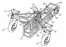
Three-wheeled motor vehicle with pivotable frame |
1986-06-03 |
Gregory Marier Wayne Warnke |
US4437535 |
US7419024 WO2005032877 US2002063011 US6641154 US5575352 |
1F1T |
||
|
Figure |
Abstract |
||||||
|
|
A three-wheeled motor vehicle having a two-part
frame construction in which a front frame member includes the front steerable
wheel assembly and the supports for the driver's seat, and the rear frame
assembly includes support for the engine and a driven pair of rear wheels.
The front and rear frames are pivotally joined to allow rotational motion of
the front frame assembly relative to the rear frame assembly about a
generally longitudinal axis, and an arcuate guide bar and associated slide
bearings are used to couple the rearmost seat supports of the front frame to
the rear frame providing desired rigidity to the composite frame structure. |
||||||
|
Patent number |
Title of
the patent |
Publication
date |
Inventor
(s) |
Documents cited by the inventor (s) |
Cited documents in search report |
Other patents where this patent is cited in
search report |
Field of
application |
|
Parking system for an articulated tricycle |
1985-12-24 |
Yasuhiko Tsukiji Yasuhisa Yanagisawa |
None |
US2617288 US3788108 US3789634 US4232537 |
EP1431097 DE3715882 US4665725 |
1F1T |
|
|
Figure |
Abstract |
||||||
|
|
A parking locking system for an articulated or
swing-type tricycle. A parking lever mounted to the handlebars of the steerable
wheel actuates a cable and a rod. The rod engages a spring loaded slideable
pin member into a hole in a plate fixed to the front frame of the steerable
wheel. If the pin is not aligned with one of the holes in the plate, the
spring will deform and the pin will slide relative to the rod. Upon further
rotation of the front handlebars to a position where the pin member is
aligned with a hole, the compression in the spring will cause the pin to
interengage with the fixed plate thus locking the front steering wheel. The
actuation of the cable interengages locking arms with a plate attached to the
front of the swing shaft and with a parking gear in the drive train,
respectively.; A spring-loaded lever resisting interengagement of the locking
arms is used to create tension in the cable and retract the locking arms when
the parking lever is deactivated. |
||||||
|
Patent number |
Title of
the patent |
Publication
date |
Inventor
(s) |
Documents cited by the inventor (s) |
Cited documents in search report |
Other patents where this patent is cited in
search report |
Field of
application |
|
Articulated tricycle |
1985-09-17 |
Katsuyoshi Kawasaki |
None |
US3029889 US4003443 |
WO9906230 WO9857838 US6050593 US6062581 (human powered) US5762351 (Human powered) US5460234 US5107950 (see Miscellaneous) US5060749 (see Miscellaneous) US5020624 US4984650 US4887688 (irrelevant) |
1F1T |
|
|
Figure |
Abstract |
||||||
|
|
An articulated tricycle of the swingable type
employing a front body and a rear body, the front body having a front wheel
and a rear body having two rear wheels mounted on an axle or axles. The rear
body includes a first body member and a second body member. The first body
member is pivoted about a longitudinal axis to the front body while the
second body member is pivotally mounted about a transverse axis to the first
body member. The second body member includes mounting for the rear wheels.
The second body member may be divided into two links to provide independent
rear suspension for the wheels. A gear train extends between an engine,
located in the first body member, and the rear axle or axles. This gear train
is shown to include a chain or belt drive and may include two such chains or
belts when the second body member employs two links.; Either the rear axle,
or, in the case of the multiple link second body member, the transverse drive
shaft may include a differential mechanism for providing some relative
pivotal movement of one rear wheel relative to the other. |
||||||
|
Patent number |
Title of
the patent |
Publication
date |
Inventor
(s) |
Documents cited by the inventor (s) |
Cited documents in search report |
Other patents where this patent is cited in
search report |
Field of
application |
|
Vehicle body tilting
system |
1985-09-04 |
Edmund Jephcott |
EP0020835 (see US4484648 ) |
EP0020835 (see US4484648 ) GB927745 GB899003 FR1143882 GB2128142 |
None |
1F1T |
|
|
Figure |
Abstract |
||||||
|
|
The system is responsive both to lateral
acceleration of the vehicle and to steering movements. The mechanism includes
tilt actuator means (11) and tilt control means (12) governed by a gravity-sensitive
device (22) and a device (25-27) responsive to steering movement. The system
maintains the vehicle body substantially in line with the resultant vector of
gravity and centripetal acceleration while cornering. The steering input
accelerates the response of the mechanism to changes of direction of the
vehicle. |
||||||
|
Patent number |
Title of
the patent |
Publication
date |
Inventor
(s) |
Documents cited by the inventor (s) |
Cited documents in search report |
Other patents where this patent is cited in
search report |
Field of
application |
|
Parking lock device for motor tricycles |
1985-08-13 |
Masahico Takenaka Taiichi Shimazaki |
None |
US2149761 IT351402 |
EP1897795 US2005139433 US2005134014 US2002030344 US2002020589 US2001020377 EP0909695 |
1F1T |
|
|
Figure |
Abstract |
||||||
|
|
A Parking lock operating device for a motor tricycle
is disclosed. The motor tricycle includes a front and rear bodies which are
equipped with a single wheel and two wheels, respectively. The motor tricycle
is also equipped with parking brake means for braking the movement of the
tricycle when stopped and means for preventing the front body from rolling
and swinging in parking. The parking lock operating device may effect both
the parking brake means and the means for preventing roll and swing motions
of the front body relative to the rear body by a single operation lever. In
addition, for burglarproof of the tricycle, a key switch cannot be pulled
apart unless the operating lever is rotated to a predetermined position after
the operation lever is lifted up for parking lock. |
||||||
|
Patent number |
Title of
the patent |
Publication
date |
Inventor
(s) |
Documents cited by the inventor (s) |
Cited documents in search report |
Other patents where this patent is cited in
search report |
Field of
application |
|
Articulated tricycle |
1984-09-04 |
Yoshinori Mita |
US472716 |
US3448992 |
US2002043422 US6129165 US6050593 EP0898517 US6062581 (human powered) US5695021 US5116293 US5020624 US4951777 US4877102 US4678053 US4674589 |
1F1T |
|
|
Figure |
Abstract |
||||||
|
|
An articulated tricycle of the swingable type
employing a front body and a rear body, the front body having a front wheel
and the rear body having two rear wheels mounted on an axle. The rear body
includes a first body member and a second body member. The first body member
is pivoted about a transverse axis to the front body while the second body
member is pivotally mounted about a longitudinal axis to the first body
member. The second body member includes mounting for the rear wheels. A gear
train extends between an engine, located in the front body, and the rear
axle. This gear train may pass through either the first body member or second
body member and includes a chain drive. Either the drive sprocket or the
driven sprocket is positioned about a constant velocity universal joint which
is in turn positioned about a transverse shaft or the transverse rear axle. |
||||||
|
Patent number |
Title of
the patent |
Publication
date |
Inventor
(s) |
Documents cited by the inventor (s) |
Cited documents in search report |
Other patents where this patent is cited in
search report |
Field of
application |
|
Three-track motorcycle with cambering main frame |
1984-03-20 |
Frank Winchell Klaus Winkelmann |
US3277840 US4020914 US4087107 US4088199 (see 2F3T) |
US2004079561 US2003141678 US5899291 US6062581 (human powered) US5107950 (see Miscellaneous) |
1F1T |
||
|
Figure |
Abstract |
||||||
|
|
Three-wheel motorcycle with cambering main frame
supporting a front steering column and front wheel. The cambering frame is
pivotally mounted on a centralized non-cambering rear support including the
engine that carries the rear suspension and laterally spaced drive wheels.
Operator footrests are mounted on rear support and automatically tilt with
the cambering frame to improve operator balance of the vehicle. |
||||||
|
Patent number |
Title of
the patent |
Publication
date |
Inventor
(s) |
Documents cited by the inventor (s) |
Cited documents in search report |
Other patents where this patent is cited in
search report |
Field of
application |
|
Rear-wheel suspension device for a tricycle vehicle |
1984-02-07 |
Shinichi Koizumi Takeshi Kawaguchi Katsuyoshi Kawasaki |
US3931989 |
None |
GB2374328 US6405823 US5338247 US4972920 US4497506 |
1F1T |
|
|
Figure |
Abstract |
||||||
|
|
A rear-wheel suspension device on a tricycle vehicle
having front and rear vehicle portions interconnected by a rolling joint
having a sleeve bearing. To provide increased stability between a pair of
rear wheels of the tricycle vehicle, a casing of the rolling joint is
pivotably mounted on a frame of the front vehicle portion for pivotable
movement. The rolling joint has a spindle connected in a fixed positional
relationship relative to axles of the rear wheels. A shock absorber is
interposed between the frame and the casing. To increase damping and vibration-isolating
ability, the casing is pivotably connected to the frame by a link, and the
shock absorber is oriented so as to be substantially perpendicular to a
straight line passing through an axis of the rear-wheel axles when they are
loaded and a pivot point at which the link is pivotably connected to the
casing.; The link and the shock absorber have respective longitudinal axes
extending substantially parallel to each other, and an engine is oriented
such that major vibrations thereof are produced in a direction substantially
at a right angle to the aforesaid longitudinal axes. |
||||||
|
Patent number |
Title of
the patent |
Publication
date |
Inventor
(s) |
Documents cited by the inventor (s) |
Cited documents in search report |
Other patents where this patent is cited in
search report |
Field of
application |
|
Oscillating link mechanism for three-wheeled motor
vehicles |
1984-01-10 |
Katsuyoshi Kawasaki |
None |
None |
US5678835 (human powered) US5109943 |
1F1T |
|
|
Figure |
Abstract |
||||||
|
|
A position adjusting means of a link mechanism which
hangingly supports a swing joint in three-wheeled motor vehicle having front
body laterally swingable relative to a rear body. The position adjusting
means includes a pair of flexible stops, one being positioned behind one end
of a sleeve member which supports a pair of link members, and the other being
positioned in front of the sleeve member. These stops are mounted onto a pair
of frame members positioned in the front body and extending in parallel along
travel direction of the vehicle, or mounted onto one of said frame members so
as to position at least one end of said sleeve between the stops. The link
members each have an upper end integrally connected to a supporting member
and a stop is secured to the lower surface of each supporting member.; The supporting
members extend in horizontal plane and opposite direction relative to the
sleeve along travel direction of the vehicle. The sleeve supports the pair of
link members and is concentrically supported by a pivotal shaft through
rubber bushes. The both ends of the pivotal shaft is secured by a pair of
brackets mounted on the pair of frame members. Upon placement of the stops
onto the frame members, the link members provide vertical orientation. |
||||||
|
Patent number |
Title of
the patent |
Publication
date |
Inventor
(s) |
Documents cited by the inventor (s) |
Cited documents in search report |
Other patents where this patent is cited in
search report |
Field of
application |
|
Wheeled vehicle with cambering front module |
1984-01-03 |
Frank Winchell Jerry Williams Clark Irwin |
None |
US2007045020 US2006086555 WO02098722 (see FR2825672) US6062581 (human powered) US5107950 (see Miscellaneous) US4877102 |
1F1T |
||
|
Figure |
Abstract |
||||||
|
|
A three-wheeled cambering vehicle having a rear
noncambering module which has a forwardly extending tongue which rotatably
supports a main and front cambering module. The cambering module carries the vehicle
operator who steers the vehicle by rotating a single front wheel about a
substantially vertical axis and additionally leans in response to vehicle
turn and his own will, the two modules are rotatable in relation to each
other about an inclined camber axis extending longitudinally of the vehicle.
The cambering module has cambering controls at a forward portion thereof to
allow the operator to physically engage the controls with his feet for
cambering the front module relative to the ground and rear modules. |
||||||
|
Patent number |
Title of
the patent |
Publication
date |
Inventor
(s) |
Documents cited by the inventor (s) |
Cited documents in search report |
Other patents where this patent is cited in
search report |
Field of
application |
|
Tubing assembly in mutually movable portions of a
three-wheeled motor vehicle |
1983-12-20 |
Katsuyoshi Kawasaki |
None |
US2922662 US4316520 |
ES2294873 EP1900623 ES2253041 ES2228230 EP1145945 EP0462615 |
1F1T |
|
|
Figure |
Abstract |
||||||
|
|
A tubing assembly provided between two movable bodies
such as front and rear body portions of a three-wheeled motor vehicle. The
front body is laterally swingable relative to the rear body and these bodies
are relatively movable along longitudinal and vertical directions thereof.
The tubing assembly includes a first flexible tubular member extending
substantially vertically and having one end connected to a first rigid
tubular member of said front body portion, a second flexible tubular member
extending substantially horizontally and having one end connected to a second
rigid tubular member of said rear body portion, and a generally L-shaped
intermediate rigid tubular member connected between said first and second
flexible tubular members. The tubing assembly is positioned outwardly offset
from a rotational center of said movable bodies and at the same longitudinal
side of said vehicle. |
||||||
|
Patent number |
Title of
the patent |
Publication
date |
Inventor
(s) |
Documents cited by the inventor (s) |
Cited documents in search report |
Other patents where this patent is cited in
search report |
Field of
application |
|
Apparatus for the operation and control of the tilt
of the body of a vehicle |
1983-01-18 |
Pierre Patin |
US3698502 FR1562248 |
US1262829 US1574691 US1821271 US2417526 US2815960 |
WO2005077683 US4448436 |
1F1T |
|
|
Figure |
Abstract |
||||||
|
|
The device in accordance with the invention operates
and controls the tilt of a body of a vehicle and is operated by a driving shaft
driven in rotation by movement of the vehicle. A rocking mechanism that is
capable of being driven in two opposite directions by the driving shaft
employs two disengageable coupling assemblies to operate rocking of the body,
each in one direction. Progressive engagement of one or other of the coupling
assemblies is operated directly by a pendular mass. Deviation of the latter
to one side or the other of a plane passing through its axis of oscillation
and parallel with the median plane of the body, causes progressive engagement
of that one of the two coupling assemblies.; This causes rocking of the body
in a direction which enables the median plane of the latter to be brought
back into the direction of the apparent vertical passing through the axis of
oscillation and the center of gravity of the pendular mass. |
||||||
|
Patent number |
Title of
the patent |
Publication
date |
Inventor
(s) |
Documents cited by the inventor (s) |
Cited documents in search report |
Other patents where this patent is cited in
search report |
Field of
application |
|
Parking apparatus for use on a three-wheeled
motorized vehicle |
1982-11-02 |
Masaki Watanabe Keiji Suzuki Goroei Wakatsuki |
None |
US684053 US3698502 US3814200 US4006916 |
EP1897795 US2006042844 EP1366973 US2002020589 DE19833478 US4909525 US4678053 US4697842 FR2582610 US4923026 US4497503 US4534439 US4462481 |
1F1T |
|
|
Figure |
Abstract |
||||||
|
|
A parking apparatus for a three-wheeled motorized
vehicle having one front wheel, two rear wheels, and a front body portion
which is transversely swingable relative to a rear body portion. The
apparatus comprises a locking mechanism provided between the front and rear
vehicle body portions for disabling the front body portion from swinging, a
parking brake mechanism operatively cooperating with a normal wheel brake, or
alternatively being independent thereof, and a common operating member for
operating both the locking and parking brake mechanisms simultaneously. |
||||||
|
Patent number |
Title of
the patent |
Publication
date |
Inventor
(s) |
Documents cited by the inventor (s) |
Cited documents in search report |
Other patents where this patent is cited in
search report |
Field of
application |
|
Stabilized motor
vehicle |
1982-07-20 |
Masaki Watanabe Hiroshi Shimoyama Keiji Suzuki |
US3776353 |
US1056073 US3016967 |
US2002151414 US2002029919 EP1145945 US2001028168 GB2307218 US4721178 US4421194 |
1F1T |
|
|
Figure |
Abstract |
||||||
|
|
A three-wheeled motorcycle having a front body
portion including a relatively low floor which carries a fuel tank and a
battery which are located on a floor having footrests, and below a reference
level tangential to the front and rear wheels at their upper edges. The fuel
tank and battery are covered with an upper hood and a lower protective cover.
With the relatively heavy fuel tank and battery being disposed at a
relatively low level, the motorcycle is stabilized for improved
maneuverability during driving and parking, and has a wide space available
for driver's activity or storing baggage. |
||||||
|
Patent number |
Title of
the patent |
Publication
date |
Inventor
(s) |
Documents cited by the inventor (s) |
Cited documents in search report |
Other patents where this patent is cited in
search report |
Field of
application |
|
Cambering vehicle |
1982-04-20 |
Frank Winchell |
US4087106 |
US3583507 US3698502 US3746118 |
WO2008060265 US2006042844 US2004144586 US2003132067 ES2232224 US6089587 US6062581 (human powered) |
1F1T |
|
|
Figure |
Abstract |
||||||
|
|
A three-wheeled cambering vehicle having a platform
for supporting the vehicle operator and having a pair of laterally spaced rear
wheels mounted thereon. The vehicle has a centralized tubular frame with a
front leg member that supports a steerable front fork and wheel assembly and
a rearward seat for the vehicle operator. A lower leg of the frame is
supported for turning movement with respect to a longitudinal roll axis by
the platform which permits the frame and front fork and wheel assembly to be
cambered by the vehicle operator as the platform remains in a predetermined
plane with respect to the support surface. |
||||||
|
Patent number |
Title of
the patent |
Publication
date |
Inventor
(s) |
Documents cited by the inventor (s) |
Cited documents in search report |
Other patents where this patent is cited in
search report |
Field of
application |
|
Three-wheel Cambering
Vehicles |
1982-03-17 |
Frank Winchell Klaus Winklemann |
None |
US2006086555 GB2394701 EP0928737 EP0282333 FR2567476 FR2528376 FR2534543 |
1F1T |
||
|
Figure |
Abstract |
||||||
|
|
A three wheel motor cycle has a main frame 70 supporting
a front steering column 96, the main frame being pivotally mounted on a rear
support frame 14 for left and right tilting movements, and an engine 18
forming a part of the rear support driving the rear wheels 20, 22; an
operator's seat 112 is supported over the rear frame on an extension of the
main frame, and operator footrests are directly supported on the rear frame
to increase the ability of the operator to balance the cycle. The mounting of
the footrests is such that they are automatically tilted in response to
tilting movements of the main frame. |
||||||
|
Patent number |
Title of
the patent |
Publication
date |
Inventor
(s) |
Documents cited by the inventor (s) |
Cited documents in search report |
Other patents where this patent is cited in
search report |
Field of
application |
|
Unilateral rear-drive type three-wheeled vehicle |
1982-02-23 |
Hitoshi Yamamoto Masaki Watanabe Koizumi Masaki |
None |
US1532465 |
US2004188167 US5474144 US4421194 |
1F1T |
|
|
Figure |
Abstract |
||||||
|
|
An improved form of three-wheeled vehicle of the
type having a front wheel arranged in the longitudinal plane of symmetry of
the vehicle and a pair of rear wheels arranged symmetrically with respect to
the vehicle plane. The pivot joint interconnecting the front and rear frames
of the vehicle has a turning axis offset from the vehicle plane to that side
of the vehicle on which the driving rear wheel is arranged and extending in a
direction inclined laterally outwardly from rear to front of the vehicle. Such
pivot arrangement is highly effective to improve the driving stability of
three-wheeled vehicles of the type concerned, without involving any
structural complication or increase in cost of production. |
||||||
|
Patent number |
Title of
the patent |
Publication
date |
Inventor
(s) |
Documents cited by the inventor (s) |
Cited documents in search report |
Other patents where this patent is cited in
search report |
Field of
application |
|
Ultra Narrow enclosed motor vehicles |
1981-01-22 |
Edmund Jephcott |
None |
US4065144 (see 1F3T) US4126322 BE548491 FR817173 FR2243103 GB1149079 FR2338836 US4020914 US4003443 |
EP1870269 (see 1F3T) WO9406642 US4621442 US4621837 GB2450740 (see 1F3T) US2007126199 WO2006130007 (see 1F3T) US2006123763 EP1571016 (see 2F3T) WO2005030559 US2003184071 WO9911507 US6015022 WO9849023 GB2279047 (see 1F3T; 2F3T) US5343973 US4998596 US4944360 US4919225 |
1F1T; 1F3T; 2F3T |
|
|
Figure |
Abstract |
||||||
|
|
A narrow enclosed motor vehicle has a chassis
supported by road-running wheels and a body structure for at least one person
mounted so as to be inclinable relative to the median plane of the vehicle and
at least a part of the chassis structure, inclination being controlled by
driver-operated pedals mounted to the inclinable section of the vehicle and
so connected that depression of either pedal causes the vehicle body to tilt
towards the same side of the median plane of the vehicle as the depressed
pedal. |
||||||
|
Patent number |
Title of
the patent |
Publication
date |
Inventor
(s) |
Documents cited by the inventor (s) |
Cited documents in search report |
Other patents where this patent is cited in search
report |
Field of
application |
|
Improvements in or relating to vehicles |
1979-08-22 |
Edmund Jephcott |
None |
None |
WO9824681 FR2646379 (see 1F3T) GB2203104 FR2528376 GB2120184 (see US4423795) USRE32031 FR2495094 |
1F1T; 1F3T |
|
|
Figure |
Abstract |
||||||
|
|
In a road vehicle which is closed-in and which has a
width which is relatively narrow as compared with the widths of vehicles
commonly used at the present time, the vehicle includes a chassis 1 supported
by road running wheels 3, a closed-in body structure (not shown) a pivotal
connection between the body structure and at least a part of the chassis
whereby relative pivotal movement can take place between the body structure
and the chassis along an axis 8 extending longitudinally of the vehicle, and
means 16 for enabling selection of the amount and sense of the relative
pivotal movement. |
||||||
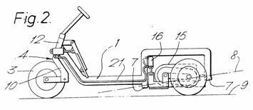
|
Patent number |
Title of
the patent |
Publication
date |
Inventor
(s) |
Documents cited by the inventor (s) |
Cited documents in search report |
Other patents where this patent is cited in
search report |
Field of
application |
|
Tricycle |
1979-07-03 |
Nobuyuki Kanno |
None |
US2966951 US3952822 |
US7543829 (human powered) US2006131092 WO2005025972 WO9824681 US5941548 DE19540578 (see WO9716339, 1F3T) US5467839 US4877102 US4909538 US4520892 USRE32031 US4480711 |
1F1T |
|
|
Figure |
Abstract |
||||||
|
|
A tricycle including a front frame, front wheel provided
on the front frame, a rear frame provided with two adjacent and parallel
wheels coupled to the front frame such that the center of the front frame is
offset to one side of the tricycle relative to the center of the rear frame.
Furthermore, if the tricycle is motorized, the motor is coupled to the rear
frame such that the center of gravity of the motor is offset to another side
of the tricycle relative to the center of the rear frame. |
||||||
|
Patent number |
Title of
the patent |
Publication
date |
Inventor
(s) |
Documents cited by the inventor (s) |
Cited documents in search report |
Other patents where this patent is cited in
search report |
Field of
application |
|
Three-wheel
motorcycle |
1977-12-27 |
Harold Parham |
US2493817 US3224523 US3447623 US3610358 US3746118 |
FR854408 US2029735 US2137947 US2353503 US2615727 US3224523 US3746118 |
US7445070 WO2005120938 US6155579 US5927424 (see WO9534459) US6056306 WO9534459 US5468009 US5421597 EP0592377 (see 2F4T) US5599033 US5318318 US5029891 US4719984 US4624469 (see 2F3T) |
1F1T |
|
|
Figure |
Abstract |
||||||
|
|
A three-wheel motorcycle having an outer frame with
rear wheels mounted on a double axle with differential therebetween for a
drive from a powerful automobile type engine together with an inner support
frame pivotally mounted from said main outer frame with said inner pivotal
frame supporting the front motorcycle type single steerable wheel. Handlebars
mounted for four-way movement together with an operator's seat and passenger
seats are also supported and mounted on the pivotal frame. A unique hydraulic
actuated tilting mechanism is associated with the two frames for
semi-automatically tilting the inner pivotal frame and the front wheel,
operator and passenger thereon, whenever the operator turns the handlebars in
order to make a turn of the vehicle and/or a turn is made which will exert
centrifugal force upon the device. A pivotally suspended mass associated with
the actuating mechanism aforesaid will automatically through the hydraulic
mechanism tilt the inner frame whenever centrifugal force acts upon said
suspended mass. This automatic operation as effected by the pivoted mass will
function as a safety factor to automatically tilt the inner frame even though
the operator neglects to do so. Other features include a fail-safe system for
the hydraulic mechanism in case of hydraulic failure, a unique shock and
spring mechanism for the inner frame, and the use of the frame tubing as part
of the overall cooling system for the high powered internal combustion
engine. |
||||||
|
Patent number |
Title of
the patent |
Publication
date |
Inventor
(s) |
Documents cited by the inventor (s) |
Cited documents in search report |
Other patents where this patent is cited in
search report |
Field of
application |
|
Lockable articulation |
1977-02-08 |
Pierre Patin |
FR1562248 US3698502 |
US1564515 US2426135 US3698502 |
DE19833478 US6129165 US6050593 US5941548 ES2064251 DE9211853 US4529055 DE3226361 US4487282 |
1F1T |
|
|
Figure |
Abstract |
||||||
|
|
A lockable articulation for permitting relative
angular rotation between a first and a second part, such for example as the
body of a three-wheeled vehicle and the rear axle of the vehicle, said
articulation comprising a hollow cylindrical drum centered and mounted on one
part, e.g. the axle, two cylindrical sector-shaped jaws arranged inside the
drum for contacting the inner surface of the drum and with their ends facing
each other, at least two facing ends defining dihedral surfaces whose angle
is outwardly opening, and means coupled to the other part, e.g.; the vehicle
body, for spreading the jaws apart into frictional engagement with the drum
to lock the other part against rotation relative to the one part, said means
including a roller interposed between the drum wall and the dihedral surface
of the jaws and a knee lever having two-pivotally connected links one of
which is pivotted on the other part and the other of which rotatably supports
the roller. |
||||||
|
Patent number |
Title of
the patent |
Publication
date |
Inventor
(s) |
Documents cited by the inventor (s) |
Cited documents in search report |
Other patents where this patent is cited in
search report |
Field of
application |
|
Tricycle |
1976-02-17 |
Yano Kensaku Kurose Makoto Nagamitsu Toshiaki |
None |
FR1471948 US2221196 US2819093 US3504934 |
EP1783023 (irrelevant) EP1674386 EP1671877 EP1431097 WO0179027 DE19833478 WO9824681 US5107950 (see Miscellaneous) US5060749 (see Miscellaneous) US4984650 US4903790 US4678053 US4666018 US4529055 US4469188 USRE32031 EP0017480 US4325565 US4159752 |
1F1T |
|
|
Figure |
Abstract |
||||||
|
|
A tricycle having a front and a rear frame
swingingly connected with each other in an axis line longitudinal of a tricycle
body and providing between both frames an elastic member serving to restore
the front frame when it is leaned against the rear frame, which is adapted to
make zero or minimum the increasing ratio of restoring force of the elastic
member when the front frame is leaned under the predetermined angle of
inclination, while, large when over the same angle, whereby the tricycle is
made safe and improved in a turning efficiency. |
||||||
|
Patent number |
Title of
the patent |
Publication
date |
Inventor (s) |
Documents cited by the inventor (s) |
Cited documents in search report |
Other patents where this patent is cited in
search report |
Field of
application |
|
Connecting device for front and rear frame of
tricycle |
1976-01-13 |
Toshiaki Nagamitsu |
FR993029 DE1224164 FR1471948 US2221196 US3698502 |
US6129165 US6050593 DE19640475 DE9211853 DE3139347 EP0017480 |
1F1T |
||
|
Figure |
Abstract |
||||||
|
|
A tricycle having a front frame supported with one front
wheel and a rear frame supported with two rear wheels, wherein the front
frame is connected with the rear frame on the axis longitudinal of the
tricycle in the relation that the front frame is capable of being inclined to
one side or the other with respect to the rear frame. The tricycle is
provided with a torsion bar arranged between the front frame and the rear
frame on the axial line so that the torsion bar is subjected to only torsion
not to complicated stresses of bending and tension. |
||||||
|
Patent number |
Title of
the patent |
Publication
date |
Inventor
(s) |
Documents cited by the inventor (s) |
Cited documents in search report |
Other patents where this patent is cited in
search report |
Field of
application |
|
Three wheeled vehicles having static and dynamic
equilibrium |
1973-12-25 |
Pierre Patin |
FR1562248 FR2031813 |
None |
US6155579 (irrelevant) US6129165 US6050593 US5927424 (see WO9534459) US6056306 US5468009 US5460399 US5318318 US5375861 US5437467 US5029891 US5040812 US4974863 US4953880 US4877102 FR2567476 US4538713 US4065145 US4006916 |
1F1T |
|
|
Figure |
Abstract |
||||||
|
|
Not available |
||||||
|
Patent number |
Title of
the patent |
Publication
date |
Inventor
(s) |
Documents cited by the inventor (s) |
Cited documents in search report |
Other patents where this patent is cited in
search report |
Field of
application |
|
One rider golf cart |
1971-09-20 |
Rolland Burton |
None |
None |
US7543829 (human powered) WO2008011705 (irrelevant) �.49 patents |
1F1T |
|
|
Figure |
Abstract |
||||||
|
|
None |
||||||
|
Patent number |
Title of
the patent |
Publication
date |
Inventor
(s) |
Documents cited by the inventor (s) |
Cited documents in search report |
Other patents where this patent is cited in
search report |
Field of
application |
|
Stabilized three-wheel
vehicle |
1971-08-24 |
Pierre Patin |
None |
US2663266 US2887322 US2920636 US3016247 US3368705 US3480098 |
EP1516806 US4072325 |
1F1T |
|
|
Figure |
Abstract |
||||||
|
|
This invention is concerned with a stabilized
three-wheel vehicle having a steering wheel at the front and two driving
wheels at the back, wherein the vehicle comprises a chassis carrying the front
steering wheel mounted on a fork with positive play, a rear framework having
two driving wheels, and a member which will pivot around the substantially
horizontal axis and is disposed between the chassis and the rear framework, a
device sensitive to resultant of weight and centrifugal force being provited
to enable the pivotal member to be locked. |
||||||
|
Patent number |
Title of
the patent |
Publication
date |
Inventor
(s) |
Documents cited by the inventor (s) |
Cited documents in search report |
Other patents where this patent is cited in
search report |
Field of
application |
|
Tricycle vehicles |
1971-06-08 |
George L. Wallis |
US3504934 |
US530552 US2105553 US2221196 US2819093 US2878032 FR1158922 |
WO2009027597 (see 2F3T) WO2005025972 US6062581 US5240267 US5121806 US4740004 US4647067 US4592441 US4469188 EP0017480 US4316520 US4278273 US4159752 US4003443 US3938609 US3995875 US3931989 |
1F1T |
|
|
Figure |
Abstract |
||||||
|
|
None |
||||||
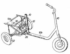
|
Patent number |
Title of
the patent |
Publication
date |
Inventor
(s) |
Documents cited by the inventor (s) |
Cited documents in search report |
Other patents where this patent is cited in
search report |
Field of
application |
|
Tricycle wheel and frame arrangement |
1970-04-07 |
Leslie George Wallis |
None |
US2792234 US3206223 US3237961 IT408719 |
EP1580105 US2005194757 US6405823 US6129165 US6050593 US5460234 US5076388 US4634137 US4529055 USRE32031 US480024 US480665 US2002047245 US4281844 DE2848905 US4065144 (see 1F3T) US4003443 US3880449 SE7404244 BE824890 NL7412112 BE816539 NL6902701 |
1F1T |
|
|
Figure |
Abstract |
||||||
|
|
None |
||||||
|
Patent number |
Title of
the patent |
Publication
date |
Inventor
(s) |
Documents cited by the inventor (s) |
Cited documents in search report |
Other patents where this patent is cited in
search report |
Field of
application |
|
|
Cycle � propulsion
par p�dales ou par moteur avec dispositif de stabilisation |
1967-05-26 |
Leslie George Wallis |
None |
None |
FR2918634 FR2280539 |
1F1T |
|
Figure |
Abstract |
||||||
|
None |
None |
||||||
|
Patent number |
Title of
the patent |
Publication
date |
Inventor
(s) |
Documents cited by the inventor (s) |
Cited documents in search report |
Other patents where this patent is cited in
search report |
Field of
application |
|
Three-wheeled motorcycle with rockable rear wheel
assembly |
1959-03-17 |
Earle G Hawke |
None |
US2027254 US2173068 US2714017 US2722428 DE929051 GB262242 SE113808 |
US7445070 WO9925603 US4592441 US4449602 DE3012912 US4281844 US4064957 US3931989 US3698502 US3504934 US3184076 |
1F1T |
|
|
Figure |
Abstract |
||||||
|
None |
None |
||||||
|
Patent number |
Title of
the patent |
Publication
date |
Inventor
(s) |
Documents cited by the inventor (s) |
Cited documents in search report |
Other patents where this patent is cited in
search report |
Field of
application |
|
Perfectionnements aux
scooters et motocycles car�n�s |
1958-06-20 |
Paul Dugelay |
None |
None |
US5927424 (see WO9534459) US4020914 |
1F1T |
|
|
Figure |
Abstract |
||||||
|
|
None |
||||||
|
Patent number |
Title of
the patent |
Publication
date |
Inventor
(s) |
Documents cited by the inventor (s) |
Cited documents in search report |
Other patents where this patent is cited in
search report |
Field of
application |
|
Suspension mechanism for motor driven vehicles and
the like |
1958-01-07 |
Homer Geiser |
None |
US880025 US1026851 US1252643 US1400286 US2116027 US2232549 US2260102 DE612038 GB467377 |
US2007095590 US6129165 US6050593 US5611555 (see 1F3T; EP0606191) US5316326 WO9114590 US3822755 US3756334 US3746118 US3698502 |
1F1T |
|
|
Figure |
Abstract |
||||||
|
|
None |
||||||