|
1900-1909 |
1910-1919 |
1920-1924 |
1925-1929 |
1930-1934 |
1935-1939 |
1945-1949 |
1950-1954 |
1955-1959 |
|
|
|
|
|
|
|
|
|
|
|
|
|
1960 |
1961 |
1962 |
1963 |
1964 |
1965 |
1967 |
1969 |
||
|
|
|
|
|
|
|
|
|
|
|
|
1970 |
1971 |
1972 |
1973 |
1974 |
1975 |
1977 |
1979 |
||
|
|
|
|
|
|
|
|
|
|
|
|
1980 |
1981 |
1982 |
1983 |
1984 |
1985 |
1987 |
1989 |
||
|
|
|
|
|
|
|
|
|||
|
1990 |
1991 |
1992 |
1993 |
1994 |
1995 |
1997 |
1999 |
||
|
|
|
|
|
|
|
|
|
||
|
2000 |
2001 |
2002 |
2003 |
2004 |
2005 |
2007 |
2009 |
||
|
|
|
|
|
WO2005077683 |
|
||||
|
2010 |
|
|
|
|
|
|
|
|
|
|
|
|
|
|
|
|
|
|
|
|
Patent number |
Title of
the patent |
Publication
date |
Inventor
(s) |
Documents cited by the inventor (s) |
Cited documents in search report |
Other patents where this patent is cited in
search report |
Field of
application |
|
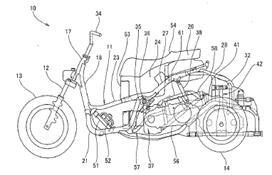
Three-wheeled motorcycle |
2010-03-04 |
Hiroshi Takeda |
? |
None |
None |
1F3T |
|
|
Figure |
Abstract |
||||||
|
|
None |
||||||
|
Patent number |
Title of
the patent |
Publication
date |
Inventor
(s) |
Documents cited by the inventor (s) |
Cited documents in search report |
Other patents where this patent is cited in
search report |
Field of application |
|
Rotating mechanical transmission for a tilting system
of the wheels of a vehicle with three or four wheels |
2010-02-11 |
Luciano Marabese |
EP1282551 (see 1F1T; WO0187689) |
None |
1F3T; 2F4T |
||
|
Figure |
Abstract |
||||||
|
|
The present invention relates to a wheel tilting
system for vehicles with three or more wheels in which at least two wheels
are set alongside on the same axle. The wheel tilting system according to the
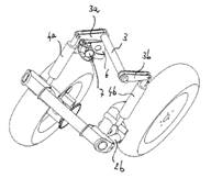
present invention comprises at least one oscillating arm (2) for each wheel
and at least one mechanical transmission (3, 3a, 3b, 4) adapted to connect
said arms (2) to one another and adapted to transmit the motion of
oscillation of said arms (2) into the motion of rotation of a connection rod
(3) about its axis. The tilting system according to the present invention it
particularly simple to be implemented and thus cost-effective as well as
operatively reliable. Furthermore, such a system have very small dimensions
and light weight. |
||||||
|
Patent number |
Title of
the patent |
Publication
date |
Inventor
(s) |
Documents cited by the inventor (s) |
Cited documents in search report |
Other patents where this patent is cited in
search report |
Field of
application |
|
Motor vehicle and rickshaw and tilting mechanism
thereof |
2010-02-11 |
Mau-pin Hsu Chia-en Lee Ta-chan Peng Chia-ming Wu |
None |
None |
None |
1F3T |
|
|
Figure |
Abstract |
||||||
|
|
A motor vehicle is provided. The motor vehicle comprises
a vehicle body, a front wheel, a rear wheel and a tilting mechanism. The
front wheel, the rear wheel and the tilting mechanism are disposed on the
vehicle body. The tilting mechanism comprises a first compensation unit, a
first arm, a first wheel, a second compensation unit, a second arm, a second
wheel, at least one pipe and a fluid. The first arm is connected to the first
compensation unit, and the first wheel. The second arm is connected to the
second compensation unit, and the second wheel. The pipe connects the first
compensation unit to the second compensation unit. The fluid flows in the
first compensation unit, the second compensation unit and the pipe, wherein
when the motor vehicle tilts, an extension length of the first compensation
unit equals to a compression length of the second compensation unit. |
||||||
|
Patent number |
Title of
the patent |
Publication
date |
Inventor
(s) |
Documents cited by the inventor (s) |
Cited documents in search report |
Other patents where this patent is cited in
search report |
Field of
application |
|
Motor vehicle with controlled inclination |
2009-09-03 |
Daniel Moulene Thierry Moulene |
None |
FR2872773 (see 2F4T) DE19738826 (automotive patent) US2006170171 (see 2F3T; WO2004056645) |
None |
1F3T ; 2F4T |
|
|
Figure |
Abstract |
||||||
|
|
The motor vehicle of the invention is provided with at
least three wheels (3) and includes a driving cab (2) capable of
accommodating a single person in the width direction. The motor vehicle
comprises a bend-balancing means that acts by the inclination of at least the
portion of the chassis (1) that bears the driving cab. According to the
invention, the vehicle is also provided with speed, acceleration and/or
inclination sensors, and the balancing means are automatically controlled
when the information supplied by the sensors is lower than a main predetermined
threshold. The invention also provides that the automatic control of the
balancing means is deactivated when the information provided by the sensors
is higher than said main threshold. |
||||||
|
Patent number |
Title of
the patent |
Publication
date |
Inventor
(s) |
Documents cited by the inventor (s) |
Cited documents in search report |
Other patents where this patent is cited in
search report |
Field of
application |
|
Vehicle with tilting suspension system |
2009-07-16 |
Luciano Marabese |
WO0244008 (see 2F3T; 2F4T) |
None |
1F3T |
||
|
Figure |
Abstract |
||||||
|
|
The present invention relates to a wheel tilting system
for vehicles with three or more wheels, wherein at least two wheels are
interconnected on the same axle. The system according to the present
invention enables a variation in the attitude of the vehicle that can be
selectively established in tilting or non-tilting mode without the disabling
of the vehicle tilting system interfering with the shock absorbing effect of
the vehicle's suspension system. The system in question consequently combines
the advantages of the simplicity and compact size of a hydraulic system in
which the tilting and the shock absorption of the wheels are controlled by an
integrated system of hydraulic cylinders, with the versatility of a system
affording the opportunity to choose the attitude of the vehicle. |
||||||
|
Patent number |
Title of
the patent |
Publication
date |
Inventor
(s) |
Documents cited by the inventor (s) |
Cited documents in search report |
Other patents where this patent is cited in
search report |
Field of
application |
|
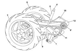
Three-wheeled motor
vehicle |
2009-01-07 |
Andrei Zavolnyi |
None |
GB2120184 (see 1F1T; US4423795) EP0606191 JP2004123080 US4484648 US2008197597 WO2004056645 (see 2F3T) |
None |
1F3T |
|
|
Figure |
Abstract |
||||||
|
|
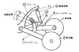
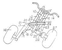
A three-wheeled motor vehicle with front steering wheel
5 and transversely spaced apart rear driving wheels 6,7 on controllable, with
sufficient freedom of oscillation in opposite directions, suspension
structure. The driver-operated pedals 22 manually change the geometrical
configuration of the rear suspension and incorporate with computer control
electromechanical gear motor power-assisted force of the pedals and provide
ride-by-wire mode, controlling vehicle in vertical position. When the pedal
22 is depressed, a toothed pawl 17 slides along a bracket shaft 16, which is
held in position by a return spring (fig 6, 20) and engages with a toothed
plate on a rocker arm (fig 6, 9). The pivotal movement of the rocker arm (9)
is transferred to synchronous movements of the swing arms (fig 3, 8) in
opposite directions to produce lateral tilt of the vehicle. |
||||||
|
Patent number |
Title of
the patent |
Publication
date |
Inventor
(s) |
Documents cited by the inventor (s) |
Cited documents in search report |
Other patents where this patent is cited in search
report |
Field of
application |
|
Suspension system |
2008-06-05 |
Nicholas Richard Shotter |
EP01998472 EP03253106 |
US2006192361 US2004113377 DE10349655 JP61278412 WO0244008 EP1362779 |
None |
1F3T ; 2F4T |
|
|
Figure |
Abstract |
||||||
|
|
A suspension system for a leanable vehicle having a pair
of laterally spaced wheels (1, 2) with hydraulic dampers (17, 18) associated
with the wheels and control means selectively operable to operate a
changeover valve (25) to cause the dampers (17, 18) to operate either
independently or simultaneously to alter the operating characteristics of the
suspension. In one position of a changeover valve (25), chambers above and
below pistons (17b and 18b) are interconnected for each damper to allow
normal tilting of the vehicle while still permitting suspension movements. In
a second position of the changeover valve (25), the chamber above piston
(17b) is interconnected with the chamber below piston (18b) and the chamber
below piston (17b) is interconnected with the chamber above piston (18b),
thereby preventing further tilting of the vehicle, whilst maintaining full
suspension movement. |
||||||
|
Patent number |
Title of the patent |
Publication date |
Inventor (s) |
Documents
cited by the inventor (s) |
Cited
documents in search report |
Other patents
where this patent is cited in search report |
Field of application |
|
Hydraulic damper system for a leanable vehicle |
2008-06-04 |
Nicholas Richard
Shotter |
EP01998472 EP03253106 |
GB2155410 DE4035128 EP1362779 WO9727071 |
None |
1F3T ; 2F4T |
|
|
Figure |
Abstract |
||||||
|
|
A suspension system for a leanable vehicle, such as
a motorcycle, has a pair of laterally spaced wheels 1 and 2 with hydraulic
dampers 18 and 19 associated with the wheels 1 and 2 and control means in the
form of a changeover valve 26 selectively operable to cause the dampers 18
and 19 to operate either independently, with line 24 connected to line 25 and
line 27 connected to line 28 or simultaneously with line 24 connected to line
27 and line 25 connected to line 28, to alter the operating characteristics of
the suspension. |
||||||
|
Patent number |
Title of
the patent |
Publication
date |
Inventor
(s) |
Documents cited by the inventor (s) |
Cited documents in search report |
Other patents where this patent is cited in
search report |
Field of
application |
|
Tiltable suspension |
2008-04-17 |
|
None |
JP2001010577 JP2006168503 JP3109191 KR200225664Y |
None |
1F3T ; 2F3T |
|
|
Figure |
Abstract |
||||||
|
|
A tiltable suspension is provided. The tiltable
suspension includes: an upper suspension arm rotatable about an upper-suspension
arm axis, which is formed at a center of a body of a vehicle and extending
toward left and right wheels; a lower suspension arm rotatable about a
lower-suspension arm axis, which is formed at the center of the body of the
vehicle and extending toward the left and right wheels; a seesaw rotatable
about the lower-suspension arm axis, having both ends thereof positioned
higher than the lower-suspension arm axis, and symmetrically extending to the
left and right; a shock absorber connecting one of the ends of the seesaw to
the lower suspension arm; a clutch controlling power delivery between the
seesaw and the body of the vehicle; and an upper-and-lower-suspension-arm
connecting member connected to each of the left and right wheels, connecting
each end of the upper suspension arm to each end of the lower suspension arm,
and including rotation axes at both ends thereof to allow the upper
suspension arm and the lower suspension arm to rotate as the left and right
wheels tilt. |
||||||
|
Patent number |
Title of
the patent |
Publication
date |
Inventor
(s) |
Documents cited by the inventor (s) |
Cited documents in search report |
Other patents where this patent is cited in
search report |
Field of
application |
|
System to control the trim of motorcycles with three
or four wheels |
2008-01-31 |
Luciano Marabese |
WO0244008 WO9727071 |
EP1362779 EP1520775 DE9414724 WO0244008 WO9727071 |
None |
1F3T; 2F4T |
|
|
Figure |
Abstract |
||||||
|
|
It is described a system to control the trim of motorcycles
with three or four wheels, including for each couple of wheels a system of
levers (1) linking the hubs of the wheels v(7, 8) belonging to the couple, a
shock absorber and one or more dampers (5) directly installed between said
wheels v(7,8), or between said system of levers v(1) and a fixed point v(51)
on the vehicle frame or chassis. |
||||||
|
Patent number |
Title of
the patent |
Publication
date |
Inventor
(s) |
Documents cited by the inventor (s) |
Cited documents in search report |
Other patents where this patent is cited in
search report |
Field of
application |
|
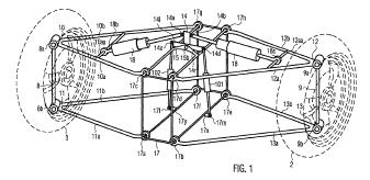
A suspension tilting module for a wheeled vehicle
and a wheeled vehicle equipped with said suspension tilting module |
2007-12-26 |
Stefano Carabelli Andrea Tonoli Andrea Festini Fabio Cavalli |
None |
GB2310838 US2260102 DE19717418 DE19619644 WO8100088 EP0528783 |
None |
2F3T; 2F4T |
|
|
Figure |
Abstract |
||||||
|
|
A tilting suspension system is provided for two
wheels (2, 3) of a vehicle (200) disposed on a common axle with said module comprising
a rigid frame (17) adapted to be firmly fixed to the chassis of the vehicle
so as to be tilted together with the whole vehicle and a tilting arm (14)
pivotally linked to said rigid frame. The tilting of the rigid frame is
obtained as a result of the counter torque arising when activating hydraulic
actuating means (101, 102) pivotally interposed between said tilting arm (14)
and said rigid frame (17), with said tilting arm being pivotally connected to
shock absorbers (18). The tilting module further comprises suspension arms
(10, 11, 12, 13) pivotally connected to the rigid frame, with said suspension
arms supporting, in cooperation with supporting uprights, the two wheels thus
allowing both tilting and steering of said two wheels.; The hydraulic actuating
means (101, 102) are actuated by an hydraulic pump (112) driven by an
electric motor (108). |
||||||
|
Patent number |
Title of
the patent |
Publication
date |
Inventor
(s) |
Documents cited by the inventor (s) |
Cited documents in search report |
Other patents where this patent is cited in
search report |
Field of
application |
|
US2010044977 EP2019772 |
Vehicle with lockable tilt system |
2007-11-08 |
Peter S Hughes Andrew H Twombly Craig Bliss |
EP1180476 (see 2F3T) US6326765 US20050092538 US6724165 |
US5762351 (Human powered) EP0876263 US2887322 US4740004 EP1180476 (see 2F3T) |
WO2009153578 EP2127920 |
1F3T; 2F3T; 2F4T |
|
Figure |
Abstract |
||||||
|
|
A vehicle that includes a vehicle body and a vehicle
support assembly. The vehicle body has a longitudinal axis and is configured
for supporting a rider thereon. The support assembly includes first (421A)
and second (421B) tilting wheels disposed respectively at different lateral
positions with respect to the longitudinal axis, a tilt-mechanism (452)
supportively associating the vehicle body from the tilting wheels to enable
the vehicle body to tilt throug\h a first tilt range with respect to a
surface on which the tilting wheels are disposed, and a tilt-limiter (456)
operably associated with the tilt-mechanism (452) to restrict the tilting of
the vehicle body to less than the first tilt range, and releasable to allow
the tilting through the first tilt range . |
||||||
|
Patent number |
Title of
the patent |
Publication
date |
Inventor
(s) |
Documents cited by the inventor (s) |
Cited documents in search report |
Other patents where this patent is cited in
search report |
Field of
application |
|
Vehicle |
2007-04-19 |
Akihiro Yanaka Yoshikazu Motozono Yasukazu Honnda |
? |
JP2005112300 JP2005082044 JP3253476 JP8034353 JP4125712 JP58018870 JP2006219033 JP2004123080 JP3026673 WO2005077683 JP2005112300 JP2005082044 |
None |
1F3T ; 2F4T |
|
|
Figure |
Abstract |
||||||
|
|
A vehicle with increased turning ability. When the vehicle
turns, left and right wheels are moved relative to a vehicle body in the
top-bottom direction, and this causes the body and the left and right wheels
to tilt to the inside of the turn. This causes force acting on a vehicle
occupant to be in the top-bottom direction of the occupant, reducing
unpleasant feeling of the occupant. Also, since the center of gravity of the
vehicle moves to the inside of the turn, turn stability is increased. |
||||||
|
Patent number |
Title of
the patent |
Publication
date |
Inventor
(s) |
Documents cited by the inventor (s) |
Cited documents in search report |
Other patents where this patent is cited in
search report |
Field of
application |
|
Self-balancing vehicle |
2006-12-07 |
Christopher Van Den
Brink |
WO9534459 (see 1F3T) WO9914099 (See 1F1T) EP0941198 NL1000161 NL20041026658 WO9924308 (See 1F1T) WO0187689 (See 1F1T) |
US6435522 (see 1F1T WO9924308) US4484648 US4660853 WO9534459 (see 1F3T) |
FR2921628 (see 2F3T) |
1F3T ; 2F3T ; 2F4T |
|
|
Figure |
Abstract |
||||||
|
|
A vehicle comprises: - at least three wheels, of
which at least two wheels are situated on either side of the centre of
gravity of the vehicle's longitudinal axis and wherein at least one of the wheels
has a steering effect on the direction of the vehicle, - a frame consisting
of a tilting frame section, wherein said frame section can rotate in the
longitudinal axis relative to the road surface, - a steering means which is
mounted so that it can rotate relative to the tilting frame section, - one or
more tilting elements which are connected to the tilting frame section and
the wheels for exerting a tilting moment and/or tilting movement between the
tilting frame section and the road surface, - a speed sensor with which the
speed of the vehicle relative to the road surface can be determined,; - a
steering sensor with which the force/the torque or the size of the steering
wheel movement for achieving a change in the direction of the steerable wheel
or the steerable wheels can be determined. Furthermore a lateral acceleration
sensor with which the lateral acceleration of the tilting frame section of
the vehicle can be determined. A method for the tilt control of this vehicle
is characterised in that the signal from the steering sensor, the signal from
the lateral acceleration sensor and the signal from the speed sensor are used
as control signal to control the tilting elements. |
||||||
|
Patent number |
Title of
the patent |
Publication
date |
Inventor (s) |
Documents cited by the inventor (s) |
Cited documents in search report |
Other patents where this patent is cited in
search report |
Field of
application |
|
|
Multitrack curve-tilting vehicle, and method for
tilting a vehicle |
2005-08-25 |
Friedrich Geiser |
FR2550507 DE01063473 DE02707562 DE03546073 DE19513649 |
US4368796 FR2450480 DE19501087 DE19738826 (automotive
patent) US2003098662 |
1F3T |
|
|
Figure |
Abstract |
||||||
|
|
The invention relates to a curve-tilting vehicle,
e.g. a three-wheeled vehicle (30), comprising means for laterally tilting (4)
at least one section (5) of the vehicle by a tilting axis (6) that runs
substantially parallel to the longitudinal axis (3) of the vehicle such that
the center of gravity of the vehicle can be displaced perpendicular to the
direction of travel when driving, especially in curves or on a sloped or
uneven ground. The inventive vehicle comprises at least one vehicle seat (8a)
that is disposed in the tilting section (5) of the vehicle and is allocated
to the driver who steers the vehicle. The vehicle further comprises means
(9a) for detecting a lateral force of the seat, which the body of the driver
applies at least to one zone of the vehicle seat (8a) in a lateral direction
(10a) extending perpendicular to the direction of travel.; In one embodiment,
the lateral force of the seat is detected using a pivotable spring-centered
vehicle seat (8a). The detecting means (9a) are effectively connected to the
lateral tilting means (4) in such a way that lateral tilting occurs in
accordance with the detected lateral force of the seat while the tilting
speed is a function at least of the lateral force of the seat and the vehicle
speed, the tilting speed increasing as the lateral force of the seat rises at
a factor that decreases as the speed of the vehicle goes up. The invention
further relates to a method for tilting such a vehicle. |
||||||
|
Patent number |
Title of
the patent |
Publication
date |
Inventor
(s) |
Documents cited by the inventor (s) |
Cited documents in search report |
Other patents where this patent is cited in
search report |
Field of
application |
|
Improvement in or relating to tilting vehicles |
2005-06-09 |
Michael Hobbs |
WO9709223 FR2522590 FR1515054 EP1459968 |
None |
1F3T |
||
|
Figure |
Abstract |
||||||
|
|
A tilting chassis vehicle has a differential gear
driving opposed half shafts (16,18). Each half shaft is connected to a
respective wheel hub. Pivoting tie rods (24,26) are provided between the
chassis (12) and these wheel hubs, and a control arm (48) is provided between
the chassis and the differential carrier to constrain movement thereof. The
arrangement gives a novel tilting vehicle with shaft drive and low centre of
gravity. |
||||||
|
Patent number |
Title of
the patent |
Publication
date |
Inventor (s) |
Documents cited by the inventor (s) |
Cited documents in search report |
Other patents where this patent is cited in
search report |
Field of
application |
|
US2005077098 US7311167 |
Swingable vehicle |
2005-04-06 |
Shinji Takayanagi Yohei Makata Hiroyoshi Kobayashi |
JP2003341725 JP2003342156 JP2003376282 |
JP63043905U EP1431083 US4786075 US3709314 US2001048207 |
WO2008011917 |
1F3T |
|
Figure |
Abstract |
||||||
|
|
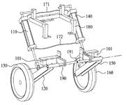
A left drive shaft (143) and a right drive shaft (144)
each include an inside constant velocity joint (191) and an outside constant
velocity joint (192) with a ball spline mechanism (193) provided between the
inside constant velocity joint (191) and the outside constant velocity joint
(192) for enabling the distance between the inside constant velocity joint
(191) and the outside constant velocity joint (192) to be contracted and
extended.; The ball spline mechanism (193) includes a spline shaft (216)
having an outer circumferential surface provided with a plurality of axial
grooves (222) extending in the axial direction, a tubular portion (213)
surrounding the periphery of the spline shaft (216) and having an inner
circumferential surface provided with a plurality of axial grooves (221)
extending in the axial direction and a plurality of balls (214) capable of
rolling while being fitted in the axial grooves (221,222). In addition, a
left lower arm (96) and a right lower arm (98) are formed into an A-shape and
are supported by a lower part of a rising portion (151) and a lower end of a
downwardly extending portion (153) of an under frame (74) via a lower
supporting shaft (157). |
||||||
|
Patent number |
Title of
the patent |
Publication
date |
Inventor
(s) |
Documents cited by the inventor (s) |
Cited documents in search report |
Other patents where this patent is cited in
search report |
Field of
application |
|
Vehicle steering
device |
2004-04-22 |
Michito Hirahara Kiyonari Kaminuma Kenji Suma Keijiro Iwao |
? |
None |
1F3T |
||
|
Figure |
Abstract |
||||||
|
|
PROBLEM TO BE SOLVED: To roll a vehicle body turning
inside with driver's intention, and to enlarge a ground camber angle of a
wheel with respect to a roll angle of the vehicle body. |
||||||
|
Patent number |
Title of
the patent |
Publication
date |
Inventor
(s) |
Documents cited by the inventor (s) |
Cited documents in search report |
Other patents where this patent is cited in
search report |
Field of
application |
|
Perfectionnement � la
suspension d�un v�hicule inclinable � trois roues |
2004-01-09 |
Philippe Girardi |
FR2550507 |
None |
1F3T |
||
|
Figure |
Abstract |
||||||
|
|
Perfectionnement
� la suspension d'un v�hicule inclinable � trois roues.La pr�sente invention a
pour objet un perfectionnement � la suspension d'un v�hicule inclinable �
trois roues. Ce perfectionnement permet de limiter les efforts dans les
moyens amortisseurs, autorise une variation de la raideur de la suspension
face � une �volution de la charge � laquelle elle est soumise et permet une
grande libert� de positionnement des moyens amortisseurs.La suspension est
constitu�e d'un levier (22) dont une extr�mit� est mont�e � pivotement par
rapport au b�ti tubulaire (2), l'autre extr�mit� de ce levier (22) �tant
reli�e de fa�on articul�e � une extr�mit� des moyens amortisseurs (16),
l'autre extr�mit� desdits moyens amortisseurs (16) �tant reli�e d� fa�on
articul�e au b�ti tubulaire (2), ce levier (22) �tant, entre ses deux
extr�mit�s,; mont� � pivotement sensiblement au milieu de la barre de liaison
transversale (15).La pr�sente invention s'applique pr�f�rentiellement � un
v�hicule destin� � un usage routier, mais peut aussi �tre appliqu�e � tous
types de v�hicules inclinables � trois roues ou plus, � des engins destin�s
aux loisirs ainsi qu'� des jouets ou � des mod�les r�duits. |
||||||
|
Patent number |
Title of
the patent |
Publication
date |
Inventor
(s) |
Documents cited by the inventor (s) |
Cited documents in search report |
Other patents where this patent is cited in
search report |
Field of
application |
|
A suspension for twinned swing- |
2003-09-24 |
Pierluigi Marconi |
|
US4974863 US4887829 |
DE202004014978 (human powered) |
1F3T |
|
|
Figure |
Abstract |
||||||
|
|
A suspension for twinned swing-axle wheels of a
tilting vehicle comprises: a first swing fork (6a) pivoted to a frame (3) of
a tilting vehicle (1) and rotatably mounting a first wheel (5a); a second swing
fork (6b) pivoted to the frame (3) parallel to the first swing fork (6a) and
rotatably mounting a second wheel (5b); a connecting rod (7a, 7b) connected
to each swing fork (6a, 6b); two rocker arms (8a, 8b) mounted on the frame
(3) through respective shafts (9a, 9b) in a plane transversal to the
direction of travel (A), and each connected through one of the connecting
rods (7a, 7b) to the respective swing fork (6a, 6b), in such manner that
vertical movements of the wheels (5a, 5b) cause the rocker arms (8a, 8b) to
rotate together with the shafts (9a, 9b) fixed to the frame (3).; The
suspension also comprises a central articulation system (10) which
kinematically connects the rocker arms (8a, 8b) so as to enable the up and
down movements of the first wheel (5a) and of the second wheel (5b) to be
controlled by imparting them in series. |
||||||
|
Patent number |
Title of
the patent |
Publication
date |
Inventor
(s) |
Documents cited by the inventor (s) |
Cited documents in search report |
Other patents where this patent is cited in
search report |
Field of
application |
|
Lean angle control for cornering motor vehicle, has
wheel suspension sensors connected to electric motor to operate screw
actuators to control angle |
2003-07-25 |
Gilbert Fauvel |
None |
EP0010019 US5060959 DE379926 |
None |
1F3T |
|
|
Figure |
Abstract |
||||||
|
|
The lean angle control for a cornering motor vehicle
has two pressure sensors (3g,d) on the suspension pivot axles of the wheels
(2g,d). The sensors engage fixed stops on the vehicle chassis and produce
electric currents with the different current values compared by an electronic
circuit and amplified (31). The control circuits actuate an electric motor to
control two screw actuators connected to the vehicle suspension arms. |
||||||
|
Patent number |
Title of the
patent |
Publication
date |
Inventor
(s) |
Documents cited by the inventor (s) |
Cited documents in search report |
Other patents where this patent is cited in
search report |
Field of
application |
|
Light motorized tricycle comprises chassis formed from
two sandwiched floors supporting compartment with front sliding and tipping
part and fixed rear part, inclination device controlling descent and raising
of rear driving arms |
2003-07-25 |
Gilbert Fauvel |
None |
DE9413375U US6149226 WO0128845 EP0217522 |
None |
1F3T |
|
|
Figure |
Abstract |
||||||
|
|
The motorized tricycle with a front steering wheel
and two rear driving wheels comprises a chassis (1) formed from two
sandwiched floors (11,12) supporting a compartment (5) in two parts, a front
sliding and tipping part (51) and a fixed rear part (52). Displacement of the
front part forwards allows access to the compartment. The tricycle is
equipped with an inclination device (4) subject to the resultant of the
transverse forces from centrifugal acceleration, aerodynamic forces and road
banking. This device simultaneously controls the descent of a rear driving
arm (3g) and the raising of the opposite arm (3d). Access to the seat (8) from
the front allows it to be protected by a shell type casing. The seat can tip
forwards with optimum damping of a frontal impact by a double shearing plate. |
||||||
|
Patent number |
Title of
the patent |
Publication
date |
Inventor
(s) |
Documents cited by the inventor (s) |
Cited documents in search report |
Other patents where this patent is cited in
search report |
Field of
application |
|
Three wheel vehicle with position stabilizer |
2001-05-25 |
Bruno Fedetto |
DE19708633 DE9414724U US4047732 |
SG126786 (no information) EP1459917 (irrelevant) |
1F3T |
||
|
Figure |
Abstract |
||||||
|
|
Three-wheel vehicle comprising a front steering wheel
(2) and a pair of rear driving wheels (3, 4), supported at the ends of two
respective oscillating arms (16, 17), the other ends of which are hinged onto
the vehicle frame (6) about a horizontal axis, said arms being reciprocally
connected through balancing means apt to transmit to one of the arms an
oscillation in a direction and to an extent opposite to those of the other
arm. Said balancing means comprise two pairs of hydraulic cylinder-piston
units (27-25 and 28-26), one for each oscillating arm (16, 17), the chambers
of the two cylinders (27, 28) being reciprocally connected through a duct
(29) of hydraulic fluid (33) under pressure.; Said balancing means comprise
means to stop the oscillation of said arms (16, 17), consisting of a control
valve (34) interposed along said duct (29) and apt to be automatically
actuated on stopping of the vehicle and/or when driving below a predetermined
critical speed, so as to stop the flow of fluid. |
||||||
|
Patent number |
Title of
the patent |
Publication
date |
Inventor
(s) |
Documents cited by the inventor (s) |
Cited documents in search report |
Other patents where this patent is cited in
search report |
Field of
application |
|
Three-wheeled motorcycle with improved cornering has
guide lever for each rear wheel fastened turnable to wheel hub and rear frame
section |
2001-05-23 |
Richard Jelke |
DE19708633 |
DE19708633 FR841661 |
None |
1F3T |
|
|
Figure |
Abstract |
||||||
|
None |
The motorcycle has two rear wheels, each held by a special
guide lever, which extends from the wheel hub to the rear section of the
frame and is fastened turnable to each of these. Each lever is extended in a
downward forward direction within the area of the hub, and the supports for
the frame are fastened moveable to the ends of the lever extensions, so that
they are pivoted in both directions. If one side of the vehicle frame is
lowered, the wheel on this side is drawn backwards and the vehicle is lowered
on this side, resulting in safe cornering. Each rear wheel can
be braked individually. |
||||||
|
Patent number |
Title of
the patent |
Publication
date |
Inventor
(s) |
Documents cited by the inventor (s) |
Cited documents in search report |
Other patents where this patent is cited in
search report |
Field of
application |
|
Rear wheel mobility system for a motorbike with three
wheels which can be inclined at an angle of more than 45 degrees |
2000-12-07 |
Roger Boedec |
None |
US4887829 FR2550507 |
None |
1F3T |
|
|
Figure |
Abstract |
||||||
|
|
An inversely symmetrical rear wheel mobility system
which is mounted on an endless screw enabling adjustment of the ground
clearance of a motor bike with three wheels which can be inclined at an angle
of more than 45 degrees. |
||||||
|
Patent number |
Title of
the patent |
Publication
date |
Inventor
(s) |
Documents cited by the inventor (s) |
Cited documents in search report |
Other patents where this patent is cited in
search report |
Field of
application |
|
A three wheeled car frame capable of inclining when
handling a curve |
1999-08-19 |
Maurizio Ficcadenti |
None |
FR2522590 US5544906 |
EP1362779 (see 2F4T) GB2374327 |
1F3T; 2F3T |
|
|
Figure |
Abstract |
||||||
|
|
A car frame for three-wheeled vehicles having two steering
front wheels and one rear wheel comprising a rigid portion and a trapezoidal
portion capable of being deformed and allowing the centre of gravity of the
vehicle and the loads applied thereon to be shifted to the inside of the
curve which is being run across, the steering being controlled by a suitable
linkage and handle bar (1), and the side inclination being controlled by the
driver by shifting his body. The front wheels steer by rotating about two
respective axes (S, S') orthogonal to the axes of rotation (AA', BB') of the
respective wheels and lie is a vertical plane passing through the centres of
the front wheels. The trapezoidal portion capable of being deformed is the
front portion, such a deformation causing the front wheels to incline together
with the rear portion where the driver's seat is located. |
||||||
|
Patent number |
Title of
the patent |
Publication
date |
Inventor
(s) |
Documents cited by the inventor (s) |
Cited documents in search report |
Other patents where this patent is cited in
search report |
Field of
application |
|
Three wheeled vehicle with tilting system |
1998-10-08 |
Maurizio Tomaselli Sergio Dalbon |
None |
None |
1F3T |
||
|
Figure |
Abstract |
||||||
|
|
The present invention relates to a small size high
mobility three wheel vehicle for light duty transportation, the main feature
of which is that it comprises a frame (2) coupled to a chassis (3) and
supporting a central front wheel (10) and two side rear wheels (15). A
suspension assembly (20) for the rear wheels (15) is moreover provided, said
suspension assembly (20) including swinging forks (21) for supporting the
rear wheels (15) interconnected by an equalizer element (30) causing the
forks (21) to swing in an opposite direction for allowing the vehicle to be
slanted on a bend. |
||||||
|
Patent number |
Title of
the patent |
Publication
date |
Inventor
(s) |
Documents cited by the inventor (s) |
Cited documents in search report |
Other patents where this patent is cited in
search report |
Field of
application |
|
Three-wheeled motor vehicle/cycle |
1998-09-10 |
Richard Jelke |
US4003443 |
None |
1F3T |
||
|
Figure |
Abstract |
||||||
|
|
The three-wheeled motorcycle has a rear wheel suspension
or support. The suspension is able to yield so that during cornering it can
move the weight more onto the wheel on the inside of the curve when this
swings-out slightly like a hammock. The motorcycle has rear-wheel drive. The
wheels are of a size so that the wheel hubs are located above the axle, where
the wheel forks are fastened to the frame, and about which the rear wheels
yield in a curve. |
||||||
|
Patent number |
Title of
the patent |
Publication
date |
Inventor
(s) |
Documents cited by the inventor (s) |
Cited documents in search report |
Other patents where this patent is cited in
search report |
Field of
application |
|
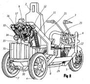
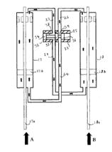
Motorcycle with more than two wheels |
1997-10-01 |
Juan Guttierez de
Cepeda |
None |
DE2137757 US2787473 FR2534543 |
None |
1F3T |
|
|
Figure |
Abstract |
||||||
|
|
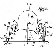
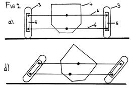
The "Motorcycle with more than two
wheels", which has been depicted in Figure 2, has two rear wheels and may
be leaned over by the rider to follow a bend, the rear wheels doing this to
the same extent as the motorcycle, consisting of the following elements: -
the chassis of the motorcycle 1 (in whose central part space is left for the
installation of the transmission differential), to which the fingers 2 and 3
are secured to which are articulated, respectively, the lower 4 and upper 5
suspension arms, to the ends of which, finally, the wheels of the motorcycle
are articulated; - the upper suspension arms (could also be the lower
suspension arms) have extensions 6 which end in fingers 7 on which the
spring/shock-absorbing assembly 8 is articulated. |
||||||
|
Patent number |
Title of
the patent |
Publication
date |
Inventor
(s) |
Documents cited by the inventor (s) |
Cited documents in search report |
Other patents where this patent is cited in
search report |
Field of
application |
|
Two rear wheel suspension device of tricycle having
two rear wheels which travels in the same way as two wheels |
1997-08-12 |
Tadashi Ishihara |
None |
None |
None |
1F3T |
|
|
Figure |
Abstract |
||||||
|
|
PROBLEM TO BE SOLVED: To obtain traveling property,
stability, and safety which are equal to or more than those of a two wheeler
during traveling by connecting two rear wheels by a differential gear and
connecting a differential central part of the differential gear on the center
of gravity of a vehicle body directly or by a buffer device to suspend two
wheels in a two rear wheel suspension method. SOLUTION: Two rear wheels 1, 2
are set to swing arms 3, 4, the swing arms 3, 4 are connected by differential
gears 5, 6, 7, and a bearing 8 which rotates a pinion 6 freely is connected
by a fixing or buffer device 9 on the center line or the line of center of
gravity of a vehicle body frame 10.; When there is a projection on a road and
one wheel rides over it, force raised by the differential gears 5, 6, 7 set
to the swing arms is received from both wheels, the force is transmitted from
the pinion part 6 to a vehicle body and is supported by a part 11 of the
pinion part 6 on the center line or the line of center of gravity. As is
shown by the vehicle body which rides over the projection on the road, its
travel amount is reduced to a half by the differential gears, and it is more
stable than a two wheeler. |
||||||
|
Patent number |
Title of
the patent |
Publication
date |
Inventor
(s) |
Documents cited by the inventor (s) |
Cited documents in search report |
Other patents where this patent is cited in
search report |
Field of
application |
|
Vehicle with a frame and at least two link arms |
1997-07-31 |
Friedrich Geiser |
FR2550507 DE3226361 |
GB2285778 EP0202842 US2887322 GB2220625 |
WO2008052539 (human powered) WO2008011917 ES2284383 WO2005113267 EP1571016 (see 2F3T) EP1561612 WO2005037637 WO02068228 (see 2F3T) WO0073127 WO9961303 |
1F3T |
|
|
Figure |
Abstract |
||||||
|
|
The invention concerns a vehicle with two adjacent link
arms (3) which support the vehicle with respect to the surface on which it is
travelling. The link arms (3) can be coupled to each other via engagement
elements (4) such that given relative positions can be secured. |
||||||
|
Patent number |
Title of
the patent |
Publication
date |
Inventor
(s) |
Documents cited by the inventor (s) |
Cited documents in search report |
Other patents where this patent is cited in
search report |
Field of
application |
|
Vehicle with at least three wheels and a suspension
system |
1997-06-19 |
Romeo Muccio |
None |
DE1063473 EP0560670 GB2155411 FR2391892 DE822487 |
FR2921628 (see 2F3T) WO03018390 GB2374327 EP1180476 (see 2F3T) WO9941136 |
1F3T |
|
|
Figure |
Abstract |
||||||
|
|
A vehicle having at least three wheels (11) with a suspension
system comprising at least two arms (10) hinged at one end thereof to the
frame of the vehicle (1, 8, 16) and at the opposite end thereof to the hub of
the respective wheel, damping and elastic members (14) hinged to said arms
and to said frame of the vehicle; the arrangement of said arms on said frame
being such that it allows the latter to be inclined inwards of a curved
trajectory and in such a way that the sum of the resulting forces applied to
said frame always passes through, or at least nearby the centre of gravity
thereof (3). |
||||||
|
Patent number |
Title of
the patent |
Publication
date |
Inventor
(s) |
Documents cited by the inventor (s) |
Cited documents in search report |
Other patents where this patent is cited in
search report |
Field of
application |
|
Conversion kit for a two-wheeled scooter |
1997-05-09 |
Siegfried Woerner |
None |
CH98009 DE817562 WO9523727 DE4103713 DE9113351U |
WO0224517 |
1F3T |
|
|
Figure |
Abstract |
||||||
|
|
In order to convert a two-wheeled scooter into a
three-wheeled scooter, an auxiliary frame (7) is provided which is secured to
the scooter frame (1) in place of the rocker arm (3). The rocker arm (3),
which supports the motor (4) and the drive wheel (6), is pivotably secured to
this auxiliary frame (7) via a bolt (13). At its opposite end the auxiliary
frame (7) supports an auxiliary rocker arm (8) via a bolt (15), the auxiliary
rocker arm (8) supporting the third wheel of the three-wheeled scooter via an
axle (16). The rocker arm (3) and the auxiliary rocker arm (8) are supported
via shock-absorbing struts (19) on a cross-member (9) which is connected to
the scooter frame (1). |
||||||
|
Patent number |
Title of
the patent |
Publication
date |
Inventor
(s) |
Documents cited by the inventor (s) |
Cited documents in search report |
Other patents where this patent is cited in search
report |
Field of
application |
|
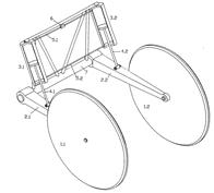
Balancing mechanism for vehicle having three wheels |
1995-08-10 |
Ernst Huber |
DE1580728 GB927745 DE745155 DE1060722 |
DE1580728 DE1060722 DE745155 DE745155 |
DE102006052041 |
1F3T |
|
|
Figure |
Abstract |
||||||
|
|
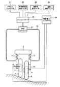
The balancing mechanism has main wheels (1.1 1.2)
that are suspended side by side on the vehicle body. The balancing
arrangement consists of a pressure cylinder system (3.1,3.2) for each wheel
suspension. The upper pressure chamber of one cylinder is directly connected
to the upper pressure chamber of the other cylinder by a pressure pipe (5.1),
which includes a blocking valve (6). Both wheel forks (2.1,2.2) are movably
mounted on an axis (7) running transversely to the vehicle longitudinal
direction. |
||||||
|
Patent number |
Title of
the patent |
Publication
date |
Inventor
(s) |
Documents cited by the inventor (s) |
Cited documents in search report |
Other patents where this patent is cited in
search report |
Field of
application |
|
Stabilization device
for vehicle |
1995-08-01 |
Pierre Patin |
US4921263 US4974863 |
US2489968 US3781031 US4921263 US4974863 US5040812 |
US2006290083 US2003038430 US6325167 US5803474 US5570570 |
1F3T |
|
|
Figure |
Abstract |
||||||
|
|
A stabilization device for a vehicle, including a primary
part resting on the ground via wheels linked respectively by a suspension
system to vertical rods of a deformable parallelogram allowing the vehicle to
incline, and a secondary part suspended from the primary part, comprising a
driver's seat and being rigidly fixed to a cross piece which carries sliding
elements fitted with free rollers which rigidly lock the cross piece with at
least one of the uprights of the deformable parallelogram to prevent the
vehicle from falling over. |
||||||
|
Patent number |
Title of
the patent |
Publication
date |
Inventor
(s) |
Documents cited by the inventor (s) |
Cited documents in search report |
Other patents where this patent is cited in
search report |
Field of
application |
|
Body tilting device of small vehicle |
1995-06-27 |
Isao Murakami |
? |
None |
WO2006049079 |
1F3T |
|
|
Figure |
Abstract |
||||||
|
|
PURPOSE:To tilt a vehicle body to the right or left
relative to a traveling device. CONSTITUTION:A body tilting device is
provided with a chassis 4 in the longitudinal direction, a steering post 5 fixed
facing upward from the front end of the chassis 4, a forward bearing 10
provided on the steering post 5, a rear bearing 12 provided on the rear part
of the chassis 4, and a small vehicle body 13 which is supported by the
forward bearing 10 and the rear bearing 12, and swayed in the vehicle lateral
direction on the swaying center axis 14 connecting the forward bearing 10 to
the rear bearing 12, and stabilizes the vehicle body 3 by swaying it in the
lateral direction. |
||||||
|
Patent number |
Title of
the patent |
Publication
date |
Inventor
(s) |
Documents cited by the inventor (s) |
Cited documents in search report |
Other patents where this patent is cited in
search report |
Field of
application |
|
Banking suspension |
1994-12-21 |
David Dovison |
None |
GB729190 GB2155411 US4484648 US4624469 |
FR2921628 (see 2F3T) EP1894753 WO2006129020 WO2006108997 WO2006003489 WO2005095195 WO2005058680 (see 2F4T) FR2858963 WO2004011324 WO0192084 WO02068228 (see 2F3T) EP1078844 EP1180476 (see 2F3T) WO9941136 |
1F3T ; 2F3T |
|
|
Figure |
Abstract |
||||||
|
|
A form of vehicular suspension which duplicates the
dynamic properities of a motor/pedal bikers suspension and which is also
capable of keeping the vehicle upright when it is moving slowly or is stationary
is achieved by having at least one pair of wheels 3 laterally disposed about
the vehicle's body 4 in conjunction with a mechanism connecting the wheel's
uprights and the body in such a manor as to allow them to rotate freely and
in unison about the wheel's contact points with the ground. Thus the machine
may be banked into corners like a bike. The vehicle's angle of lean is
controlled by use of wheel gyroscopic forces. At low speed and when
stationary the mechanism is locked in rotation relative to the body and thus
the vehicle becomes in effect a narrow car.; As the rider/driver does not
have to be able to touch the ground with his feet to stabilise the vehicle,
it may be fully enclosed, and therefore has the potential to be as safe as
car. |
||||||
|
Patent number |
Title of
the patent |
Publication
date |
Inventor
(s) |
Documents cited by the inventor (s) |
Cited documents in search report |
Other patents where this patent is cited in
search report |
Field of
application |
|
Laterally-leaning three wheeled vehicle. |
1994-11-30 |
Marco Doveri |
US4484648 WO8503678 |
GB775405 WO8503678 CH657585 |
EP1571016 (see 2F3T) WO2005058680 (see 2F4T) WO2005037637 US2004227321 EP1431097 EP1378428 WO9709223 |
1F3T |
|
|
Figure |
Abstract |
||||||
|
|
A three wheeled vehicle comprising a single wheel
(30) mounted on a chassis (8) connected to two substantially parallel wheels
(1) by means of an articulated suspension and a handlebar (17) mounted on
steering means (31) connected to the chassis (8) and to at least one of said
wheels (30). The handlebar (17) is pivotally jointed to said steering means
(31) about a substantially longitudinal axis (A), and actuating means (18)
connected to the handlebar (17) transmits the rotation of the latter about the
axes (A) to said articulated suspension which is subjected to an inclination
relative to a medium plane with respect to said wheels. The articulated
suspension comprises a rocking beam (6) pivotally connected to the chassis
(8); shock absorbing rods (4) pivotally jointed to the rocking beam (6) and
to supporting arms (2) of the wheels (1), a stabilizing device having a
double acting cylinder (12) operated by hydraulic means by actuating means
(18) moved according to the position of the handlebar (17) with respect to
said longitudinal axis (A). A more natural driving is allowed similarly to
the driving of two wheelers. |
||||||
|
Patent number |
Title of
the patent |
Publication
date |
Inventor
(s) |
Documents cited by the inventor (s) |
Cited documents in search report |
Other patents where this patent is cited in
search report |
Field of
application |
|
Wheeled vehicle comprising an oscillating axle and
an articulated rocking lever having locking possibilities. |
1994-07-13 |
Carlos Calleja |
None |
FR1562248 US4887829 FR2550507 FR2277261 |
WO2008052539 EP1362779 (see 2F4T) EP1346907 WO0073127 EP1070658 (see 1F1T) EP0911248 FR2755933 (see Miscellaneous) |
1F3T
|
|
|
Figure |
Abstract |
||||||
|
|
The "articulated balancer with oscillating axle
and having locking possibilities" provides dynamic stability and static
balance in curves to light-weight, narrow vehicles having a high center of
gravity. Its application focuses on a vehicle having three wheels, one in
front and two in the rear, which vehicle rivals in its maneuverability a
motorcycle, offering a higher levels of safety and convenience than
conventional motorcycles. The stability in curves is obtained by enhancing
the lateral tilting of the vehicle. For this, each rear wheel must allow an
up or down motion; each of these motions is opposite to the other but to the
same extent. By means of "ball-and-socket" hinged joints, two
connecting rods connect the balancer with the rear swinging forks, converting
the balancer's rotation to an up-and-down motion of the latter.; The balancer's
axle allows an oscillation motion controlled by a shock absorber, that
provides the rear suspension of the vehicle. The static balance and certain
characteristics of its dynamic behavior are obtained by locking the rotating
of the balancer. |
||||||

|
Patent number |
Title of
the patent |
Publication
date |
Inventor
(s) |
Documents cited by the inventor (s) |
Cited documents in search report |
Other patents where this patent is cited in
search report |
Field of
application |
|
Improvement to the suspension of an inclinable
vehicle with three wheels |
1993-02-19 |
Philippe Girardi |
FR2550507 US4484767 |
EP1070658 (see 1F1T) |
1F3T |
||
|
Figure |
Abstract |
||||||
|
|
Suspension device for an inclinable vehicle with
three wheels comprising a chassis (10), a front wheel (12) and two rear
wheels (14) each mounted at the end of a trailing link (28, 30) which is articulated
with respect to this chassis, characterised in that it comprises at least one
load-transmission element (42) which can move in terms of rotation with
respect to this chassis, shock absorbing means (44) interposed between the
chassis and the trailing links, and driven displacement means (46) interposed
between the two trailing links. |
||||||
|
Patent number |
Title of
the patent |
Publication
date |
Inventor
(s) |
Documents cited by the inventor (s) |
Cited documents in search report |
Other patents where this patent is cited in
search report |
|
|
Vehicle with positive inclination on curve - |
1992-06-17 |
Ernst Dipling Hoermann |
DE3044899 DE3711554 |
DE3711554 DE3044899 |
WO2005095195 DE10315404 DE10235576 DE19905419 DE4423859 |
1F3T |
|
|
Figure |
Abstract |
||||||
|
None |
The steerable vehicle has three or four wheels. The
driver can cause the wheels to lean at an angle when negotiating a curve in a
manner similar to that used by the rider on a two wheeled vehicle. The vehicle
frame (1) has left (RL) and right (RR) wheels which tilt from the vertical as
one spring (4) is expanded and the other (5) is compressed. USE/ADVANTAGE -
Vehicle with a positive curve inclination which is stable in the rest
position and which can be adapted to a variety of load carrying requirements. |
||||||
|
Patent number |
Title of
the patent |
Publication
date |
Inventor
(s) |
Documents cited by the inventor (s) |
Cited documents in search report |
Other patents where this patent is cited in search
report |
Field of
application |
|
Three-wheel vehicle |
1992-05-26 |
Robert Miller |
US4377215 US4373743 US4550926 US3746118 US4600216 US4624469 US4717164 (human
powered) US2787473 US4045075 US4453763 US2507421 US2612964 US3575251 US2955872 US3594036 US3550948 |
US2126642 US2967062 US3008729 US3154320 US3820812 |
WO2007119978 WO2007119917 WO2007041095 WO02058949 US2003116930 US2002148664 FR2819753 US6250649 (see 2F3T; WO9849023) US6276480 US6206383 US6244190 US5899291 DE19716506 US5927424 US5845896 US5772224 US5743561 WO9615006 US5580089 US5495905 US5529324 |
1F3T |
|
|
Figure |
Abstract |
||||||
|
|
A three-wheel vehicle apparatus has one front wheel
and two rear wheels to improve safety of operation, including a novel
tilt-and-bank mechanism, front wheel suspension, safety frame, aerodynamic
body design, and sliding doors. The tilt-and-band mechanism employs a tilt
bar connected to hydraulic cylinders and spring/shock units mounted on the
wheels which automatically tilt and bank the vehicle in turns. The front
wheel suspension mounts the front wheel on a trailing arm and uses a reaction
arm connected to a pivot pin in front of the wheel for better handling of
centrifugal forces in turning. The safety frame employs three crosswise roll
bars connected together by three longitudinal bars and connectors, all in
turn connected to a complete wraparound bumper.; This vehicle is made
aerodynamically more efficient by a pointed nose and a new upswept tail that
eliminates rear drag at high speeds. Additionally, doors which can be opened
and remain open at high speeds are roller mounted on the outside of the passenger
compartments. The improved vehicle is designed to make the use of three-wheel
vehicles on today's highways safe and reliable. |
||||||
|
Patent number |
Title of
the patent |
Publication
date |
Inventor
(s) |
Documents cited by the inventor (s) |
Cited documents in search report |
Other patents where this patent is cited in
search report |
Field of
application |
|
Self-propelled balancing three- |
1991-03-12 |
Frank Miksitz |
US3480098 US4088199 (see 2F3T) US4126322 US2503106 US2767800 US2771145 US2820524 |
US2435021 US2503106 US2539490 US2583250 US2767800 |
US2004160030 US2003111279 US6286846 US6276480 US6089339 US5762351 (Human powered) US5586031 US5513865 US5330214 US5169166 |
1F3T |
|
|
Figure |
Abstract |
||||||
|
|
A self-propelled, three-wheeled vehicle includes a
power-driven single front wheel used also for steering the vehicle and two
transversely spaced apart rear wheels. The front wheel is rotatably mounted
on a front frame which is pivotally connected to a rear frame to allow
steering movement of the front frame. The rear wheels are connected to the
rear frame, which supports the rider or riders, by a parallelogram-type
balancing linkage which allows the vehicle frames and the rider to lean into
turns and also to remain upright when the vehicle passes over or is parked on
laterally inclined terrain. The front wheel is driven by one or more
hydraulic motors supported by the front frame. Hydraulic pressure to the
motor(s) is supplied from an engine-driven pump assembly supported by the
rear frame. |
||||||

|
Patent number |
Title of
the patent |
Publication
date |
Inventor
(s) |
Documents cited by the inventor (s) |
Cited documents in search report |
Other patents where this patent is cited in
search report |
Field of
application |
|
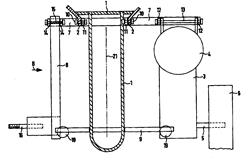
Stabilization device for inclinable vehicle |
1990-12-04 |
Pierre Patin |
US3601213 US3781031 FR2600612 |
US1688579 US2152938 US2788968 US2954833 US2960941 |
AU2002308429 US7343997 US2004160030 EP1403172 EP1346907 US5873586 US5611555 (see EP0606191) US5437467 US5040812 |
1F3T |
|
|
Figure |
Abstract |
||||||
|
|
The device comprises a secondary part (II) mounted
rotatable upon the primary part (I), a suspension system with a parallelogram,
comprising two lateral vertical rods (3a, 3b) parallel to median plane (P1 )
and two parallel equalizers (2a, 2b) articulated on the primary part (I), and
a rotation-multiplying system comprising a cross-bar (8) and two arms (10a,
10b) mounted upon both lateral rods (3a, 3b), each of them finding a support
upon the end of the controlling cross-bar (8) opposite to the corresponding
lateral rod (3a, 3b).; According to the invention, each transversal arm (10a,
10b) is subtituted by a sliding arm or consol (11a, 11b) linked to the
corresponding lateral rod (3a, 3b,) by a sliding linkage (13a, 13b)
perpendicularly to said rod, said sliding linkage comprising means (12, 18)
allowing selective control of locking or unlocking of the sliding arm in relation
with the orientations of median planes (P1, P2) of both parts of the vehicle
in relation with the apparent vertical. |
||||||
|
Patent number |
Title of
the patent |
Publication
date |
Inventor
(s) |
Documents cited by the inventor (s) |
Cited documents in search report |
Other patents where this patent is cited in
search report |
Field of
application |
|
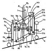
Hydraulic device for controlling the roll of an
inclinable three- |
1990-11-02 |
Philippe Girardi |
None |
FR2348844 |
ES2284383 WO02068228 (see 2F3T) US6435522 (see
1F1T WO9924308) WO9961303 EP0844118 US5542705 |
1F3T |
|
|
Figure |
Abstract |
||||||
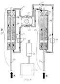
|
|
The vehicle is equipped with a front wheel 1 and with
two rear wheels 2 and 3, with a rear suspension equipped with a balance arm 8
the rotation of which brings about the inclination of the vehicle, controlled
by a double-acting hydraulic thrust cylinder 9 supplied by the output from a
pump passing through a distributor controlled by the driver. The hydraulic
circuit operates as an open centre; it is equipped with controlled non-return
valves on each supply to the thrust cylinder 9. The control circuit for the
valves is equipped with solenoid valves allowing them to be isolated, when
stationary and at low speed, beyond an inclination threshold given by
end-of-travel sensors arranged on the rod of the thrust cylinder 9.; Beyond a
speed threshold, the effect of the valves is cancelled out by virtue of a pressure
difference generated by the presence of a nozzle on the return to tank
circuit, the effects of which are managed by a solenoid valve which is
controlled by electronics 25 interpreting the signals from a speed sensor 26
located on the front wheel. In the same way, the supply to the end-of-travel
sensors is eliminated so that the inclination is no longer limited. |
||||||
|
Patent number |
Title of
the patent |
Publication
date |
Inventor
(s) |
Documents cited by the inventor (s) |
Cited documents in search report |
Other patents where this patent is cited in
search report |
Field of
application |
|
Inclinable vehicule |
1990-05-01 |
Pierre Patin |
FR1562248 FR1031813 US3480098 FR828405 FR1207733 |
US1688579 US2152938 US2788986 US2954833 US2960941 |
WO2007103392 SG126786 US2006123763 FR2872772 WO2005077683 FR2858963 US2004251655 US6149226 US5921338 US5873586 US5762351 (Human powered) US5437467 US5116069 US4974863 |
1F3T |
|
|
Figure |
Abstract |
||||||
|
|
This invention relates to an inclinable vehicle
having three or more wheels. The invention provides a stabilizer system for
the vehicle so that the stationary vehicle does not fall. The vehicle comprises
a primary part including two wheels (1a, 1b) and a distortable suspension
structure (2) connecting the wheels, and a structural member (4) mounted on a
chassis member to tilt with the suspension structure. The tilting rotates an
arm (5) with a multiplication ratio, and a roller on the arm (5) runs on a
cross-member (19). The secondary part (6) of the vehicle slides on the
structural member (4) and is carried by the cross-member (19) so that
rotation of the arm (5) on tilting of the vehicle lifts the secondary part
and raises the overall center of gravity of the vehicle. In a varient, the
rise of the center of gravity is obtained by rotation of the secondary part
of the vehicle.; A clutch may be provided to disengage the stabilizer while
the vehicle is moving. |
||||||
|
Patent number |
Title of
the patent |
Publication
date |
Inventor
(s) |
Documents cited by the inventor (s) |
Cited documents in search report |
Other patents where this patent is cited in
search report |
Field of
application |
|
Rear wheel suspension system for a tricycle vehicle |
1989-12-19 |
Curtis Prince |
None |
US3606374 US3792748 US4375293 US4478305 |
WO2008052539 US2008169149 DE102006052041 US2007075514 US2005221936 US2005167174 US7343997 US2007193815 US2004188167 US2004160030 US2004035628 EP1362779 EP1346907 US2002180177 US2002056968 WO0073127 US6293574 US5692577 DE4423859 WO9420356 US5611555 GB2279047 US5326121 DE4204191 US5116069 |
1F3T |
|
|
Figure |
Abstract |
||||||
|
|
A three wheeled vehicle having one front wheel and
two rear wheels. The front wheel is for steering. Each rear wheel is rotatably
mounted to a swing arm means. The two swing arms are pivotably mounted to the
frame. The swing arms are connected to each other through a rocking arm
assembly. The rocking arm is pivotably connected to the frame with a roll
joint. The operator has the ability to lean the vehicle while negotiating
curves. The vehicle can be kept upright while traversing a slope. |
||||||
|
Patent number |
Title of
the patent |
Publication
date |
Inventor
(s) |
Documents cited by the inventor (s) |
Cited documents in search report |
Other patents where this patent is cited in
search report |
Field of
application |
|
Motorised tricycle with independent rear wheels |
1988-12-16 |
Louis Perrin |
US4003443 FR2550507 |
FR2534543 FR2550507 BE548491 EP0009358 |
EP1884457 (see 2F4T) WO9961303 US5692577 |
1F3T |
|
|
Figure |
Abstract |
||||||
|
|
The tricycle comprises a first 3 and a second 4 rear
wheel which are offset laterally on each side of the chassis and mounted on
transverse shafts 5, 6 at the rear end of a first 7 and a second 8 trailing
lateral arm themselves articulated according to a transverse shaft 9 of the
chassis via their front end; connecting rods 13, 19 connect the lateral arms
to the ends of a transverse balance arm 18 connected at its middle 24 to the
chassis 1 by a compression spring/damper assembly 26, 27 and guidance means. |
||||||
|
Patent number |
Title of
the patent |
Publication
date |
Inventor
(s) |
Documents cited by the inventor (s) |
Cited documents in search report |
Other patents where this patent is cited in
search report |
Field of
application |
|
Devices for the stabilization of an inclinable
vehicle. |
1988-01-07 |
Pierre Patin |
FR1562248 FR2031813 US3480098 FR828405 FR1207733 |
FR776107 FR2486899 US3794351 EP0004230 |
US6149226 US4974863 |
1F3T |
|
|
Figure |
Abstract |
||||||
|
|
Stabiliser device for an inclinable vehicle consisting
of a deformable primary part connected to the ground and in which a carrying
element 4 rotates about an element 2b when the vehicle is inclined, and a
carried element 19 connected to a secondary part which can move with respect
to the primary part is raised during this inclination by means of a
rotation-multiplication system acting on a carrying arm 5, so that the centre
of gravity G of the whole vehicle is itself raised during such an inclination
movement, thus giving the vehicle stability. |
||||||
|
Patent number |
Title of
the patent |
Publication
date |
Inventor
(s) |
Documents cited by the inventor (s) |
Cited documents in search report |
Other patents where this patent is cited in
search report |
Field of
application |
|
|
Scooter with two rear wheels swinging in opposite
directions |
1987-10-22 |
Adolf Fichtner |
None |
None |
EP1884457 (see 2F4T) FR2841209 WO02098722 (see FR2825672, 1F1T) FR2755933 (see Miscellaneous) DE19540578 (see WO9716339) |
1F1T 1F3T |
|
Figure |
Abstract |
||||||
|
|
In order to eliminate the risk of the motorcycle
falling over and the three-wheeled vehicle tipping over, the two rear wheels
of the scooter with a cab swing parallel to the plane of symmetry of the vehicle,
the style of driving the motorcycle is preserved, the vehicle enters at an
inclination (optionally up to a stop) into the curve. In the position of
rest, the vehicle is locked against inclination to the side, it behaves,
likewise in first gear, as a three-wheeled vehicle. On changing up to second
and the higher gears the lock is released, the vehicle then behaves as a
motorcycle. When changing down to first gear the lock again comes into
operation, the vehicle can be parked as a three-wheeled vehicle. By means of
two pedals coupled to the rear wheels the driver may at any time also have an
influence on the position of the vehicle. The feet are no longer used for
support on the ground, the vehicle may be provided with any desired
protection against the weather up to the vehicle body being fully closed
(with heating), already tested in 1946 (including two people spending a night
in the vehicle). |
||||||
|
Patent number |
Title of
the patent |
Publication
date |
Inventor
(s) |
Documents cited by the inventor (s) |
Cited documents in search report |
Other patents where this patent is cited in
search report |
Field of
application |
|
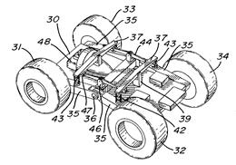
Vehicle suspension |
1987-03-03 |
Daniel Paquette Real Paquette Roger Paquette |
US2417019 US2473519 |
US1978498 US2417019 US2473519 US3175637 US3266815 |
US2006290083 US2006123763 US2005257965 US2004160031 US2004160030 US6625967 US6357766 WO0009913 US6305487 US6279931 US5921338 WO9115375 US4923257 US4881748 |
1F3T 2F4T |
|
|
Figure |
Abstract |
||||||
|
|
The suspension includes a pair of arms independently
pivoted to opposite sides of the vehicle chassis at one end for up-and-down
movement, each arm rotatably carrying a ground-engaging wheel of the vehicle at
its free end. Each arm extends in the same direction from its pivoted end,
longitudinally of the chassis. A compression spring contacts and upwardly
extends from each arm at a distance from its pivoted end, and a load transfer
lever is fulcrumed at its center to the chassis; extends transversely of the
latter; and its outer ends overly and contact the top of the respective
compression springs. The suspension system is applicable to three- and
four-wheel motor vehicles. Preferably, the arms are hollow and serve to house
part of a transformation mechanism to the wheels, the latter being the
driving wheels.; In a four-wheel vehicle in accordance with the invention,
there is further provided an additional load transfer lever disposed on each
side of the vehicle chassis and extending longitudinally of the same, with
their ends underlying and having a slidable connection with the first-named
transfer levers adjacent the springs. |
||||||
|
Patent number |
Title of
the patent |
Publication
date |
Inventor
(s) |
Documents cited by the inventor (s) |
Cited documents in search report |
Other patents where this patent is cited in
search report |
Field of
application |
|
Motorised tricycle with independent rear wheels |
1985-02-15 |
Pierre Devaux |
US4003443 |
BE548491 EP0020835 (see 1F1T) US3245490 DE1430927 US3261621 |
EP1362779 (see 2F4T) WO0073127 WO9961303 FR2755933 (see Miscellaneous) US4740004 |
1F3T |
|
|
Figure |
Abstract |
||||||
|
|
This tricycle is of the type in which the two rear
wheels 6, linked to means for rotatably driving, are mounted free to rotate at
the rear end of drawn lateral arms 4 which, articulated by their front end at
5 onto the chassis 2 of the vehicle, are each linked to one of the ends of a
transverse and horizontal balance bar 7, itself articulated about a
longitudinal axis 8. According to the invention the balance bar 7 on the one
hand is articulated on the rear part of a pivoting cradle 9 which,
articulated by its front part and about a transverse axis 10 on the chassis 2
of the tricycle, is linked to this chassis by a central suspension 20, and,
on the other hand, is linked to the drawn arms 4 by connecting rods 13 of
which the link with these drawn arms and with the ends of the balance bar is
ensured by constant velocity joints. |
||||||

|
Patent number |
Title of
the patent |
Publication
date |
Inventor
(s) |
Documents cited by the inventor (s) |
Cited documents in search report |
Other patents where this patent is cited in
search report |
Field of
application |
|
Syst�me de suspension
pour v�hicule � organes d�appui inclinables et v�hicule s�y rapportant |
1983-09-09 |
Jacques Jambon |
None |
BE357960 SU706259 DE2707562 DE1214100 US3408088 |
WO2005037637 WO2005051689 EP1362779 (see 2F4T) FR2821048 EP1070658 (see 1F1T) WO9941136 WO9502385 |
1F3T |
|
|
Figure |
Abstract |
||||||
|
|
Syst�me
de suspension pour v�hicule reposant sur une surface d�appui par
l�interm�diaire de roues 4 constituant au moins une paire sym�trique au
repos, comprenant un essieu principal 1 articul� sur le v�hicule en son
milieu, et deux barres lat�rales 2 o� sont fix�es les roues 4. |
||||||
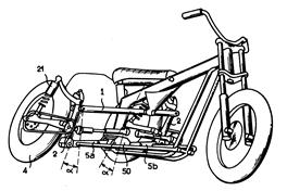
|
Patent number |
Title of
the patent |
Publication
date |
Inventor
(s) |
Documents cited by the inventor (s) |
Cited documents in search report |
Other patents where this patent is cited in
search report |
Field of application |
|
Ultra Narrow enclosed motor vehicles |
1981-01-22 |
Edmund Jephcott |
None |
US4065144 US4126322 US4368796 BE548491 FR817173 FR2243103 GB1149079 FR1158922 US4064957 FR2338836 US4020914 US4003443 |
WO9406642 US4621442 US4621837 US2007126199 US2006123763 EP1571016 (see 2F3T) WO2005030559 US2003184071 WO9911507 US6015022 WO9849023 US5343973 US4998596 US4944360 US4919225 |
1F1T; 1F3T; 2F3T |
|
|
Figure |
Abstract |
||||||
|
|
A narrow enclosed motor vehicle has a chassis
supported by road-running wheels and a body structure for at least one person
mounted so as to be inclinable relative to the median plane of the vehicle and
at least a part of the chassis structure, inclination being controlled by
driver-operated pedals mounted to the inclinable section of the vehicle and
so connected that depression of either pedal causes the vehicle body to tilt
towards the same side of the median plane of the vehicle as the depressed
pedal. |
||||||
|
Patent number |
Title of
the patent |
Publication
date |
Inventor
(s) |
Documents cited by the inventor (s) |
Cited documents in search report |
Other patents where this patent is cited in search
report |
Field of
application |
|
Improvements in or relating to vehicles |
1979-08-22 |
Edmund Jephcott |
None |
None |
WO9824681 GB2203104 US4541501 FR2528376 GB2120184 (see 1F1T; US4423795) USRE32031 FR2495094 |
1F1T; 1F3T |
|
|
Figure |
Abstract |
||||||
|
|
In a road vehicle which is closed-in and which has a
width which is relatively narrow as compared with the widths of vehicles
commonly used at the present time, the vehicle includes a chassis 1 supported
by road running wheels 3, a closed-in body structure (not shown) a pivotal
connection between the body structure and at least a part of the chassis
whereby relative pivotal movement can take place between the body structure
and the chassis along an axis 8 extending longitudinally of the vehicle, and
means 16 for enabling selection of the amount and sense of the relative
pivotal movement. |
||||||
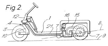
|
Patent number |
Title of
the patent |
Publication
date |
Inventor
(s) |
Documents cited by the inventor (s) |
Cited documents in search report |
Other patents where this patent is cited in
search report |
Field of
application |
|
Cambering vehicle |
1977-12-27 |
Frank Winchell |
None |
US2152938 US2609884 US2696387 US2887322 US2936034 |
US2004160030 GB2394701 US2003102657 GB2203104 US4903790 US4535869 US4368795 US4484648 US4283074 US4293052 |
1F3T |
|
|
Figure |
Abstract |
||||||
|
|
A narrow track cambering vehicle having a steerable
front wheel and a pair of laterally separated rear wheels suspended on
trailing arms mounted for independent swinging movement in separate and
parallel planes. The arms form part of a cambering system controlled by
cables and tillers actuated by foot pedals which allow the operator to vary
vehicle camber independent of steering to maximize vehicle cornering through
a wide range of turns at varying speeds. |
||||||
|
Patent number |
Title of
the patent |
Publication
date |
Inventor
(s) |
Documents cited by the inventor (s) |
Cited documents in search report |
Other patents where this patent is cited in
search report |
Field of
application |
|
Apparatus to reduce the effect of lateral forces
during turns and/or one- |
1977-09-27 |
Heinz Flaig |
DE1455101 |
US2480934 US3071366 US3490786 US3589700 US3666286 |
US6036200 WO8904262 US4600216 US4923014 US4616163 |
1F3T |
|
|
Figure |
Abstract |
||||||
|
|
The invention covers an apparatus to reduce the effect
of lateral forces during turns and/or one-sided or uneven loads on persons in
a vehicle, whereby the chassis is provided with a feeler responding to
lateral acceleration and inclination respectively, and the initial signal of
a regulator arranged at the starting point of the feeler influences the
device to tilt the chassis versus the carriage around an axis which is
parallel with the longitudinal axis of the vehicle. |
||||||
|
Patent number |
Title of
the patent |
Publication
date |
Inventor
(s) |
Documents cited by the inventor (s) |
Cited documents in search report |
Other patents where this patent is cited in
search report |
Field of
application |
|
Multiple wheel motorcycle suspension and drive
system |
1977-01-18 |
Gordon Boughers |
US3583727 (see 1F1T) US3572456 US3504934 US2521986 US2887322 |
US2038843 US2521986 US2633926 US2887322 US3024860 |
US7343997 US2004188167 US2004160030 US2005098370 GB2407541 WO2004108462 US6367824 US6286619 ES2089967 US5611555 (see EP0606191) US5040812 US4974863 US4877102 US4647067 US4541501 |
1F3T |
|
|
Figure |
Abstract |
||||||
|
|
An independent rear suspension and drive system for
a motorcycle having a steerable front wheel and a laterally mounted pair of rear
wheels, including a transverse driveshaft having a differential connection
with the engine, a pair of trailing-links journaled on the drive-shaft and
mounting the respective rear wheels pivotally about the driveshaft, a pair of
driveshaft output sprockets respectively on opposite sides of the
differential, a pair of chains operatively connecting the driveshaft output
sprockets with respective wheel drive sprockets, and a transverse arm
centrally pivoted to the frame and having at each end a dashpot connecting to
a respective trailing link; associated dashpot spring means is arranged to be
determinative of the combined trailing link positions relative to each other,
but not to the motorcycle frame. |
||||||
|
Patent number |
Title of
the patent |
Publication
date |
Inventor
(s) |
Documents cited by the inventor (s) |
Cited documents in search report |
Other patents where this patent is cited in
search report |
Field of
application |
|
Wheel-support structure in vehicles |
1976-06-22 |
Carling Allen |
None |
US1238752 US1385417 US2458400 US2551314 US2774435 |
US2006237219 US2006237218 US2006237217 WO0196143 US5960901 DE4423859 US4998596 US4600216 US4546997 US4368796 WO8100088 FR2413994 US4133551 US4088199 (see 2F3T) |
1F3T |
|
|
Figure |
Abstract |
||||||
|
|
A balance suspension system for three-wheel vehicles
wherein such system is applicable in particular to the
oppositely-reciprocating related wheels of the vehicle. The system is
designed such that the vehicle tends to maintain an essentially horizontal position,
relative to its transverse axis, even though wheels may pass over bumps or
dips or the vehicle itself may be traversing sloping terrain. Structure is
provided such that a vertical movement in one of the oppositely-reciprocating
wheels is offset by an opposite movement in the remaining wheel whereby the
transverse axis of the vehicle is essentially maintained on a horizontal
axis. Such precludes the vehicle from dipping or spilling. Further provision
is made so that, as the vehicle is cornering, the transverse orientation of
the vehicle dips inwardly, tending to oppose centrifugal force and thereby
maintain the integrity of vehicle travel. |
||||||
|
Patent number |
Title of
the patent |
Publication
date |
Inventor
(s) |
Documents cited by the inventor (s) |
Cited documents in search report |
Other patents where this patent is cited in
search report |
Field of
application |
|
Bankable tricycle
type vehicle |
1971-03-30 |
Arthur Healy |
None |
US1457025 US2415928 US3154164 US3480098 GB191011300 |
US7487985 US2006249921 GB2407541 US5611555 (see EP0606191) DE4204191 US4998596 US4360224 (see 2F3T) US4165093 US4166631 US4123079 US4088199 (see 2F3T) US4065144 US4003443 US3746118 |
1F3T |
|
|
Figure |
Abstract |
||||||
|
|
Not available |
||||||
|
Patent number |
Title of
the patent |
Publication
date |
Inventor
(s) |
Documents cited by the inventor (s) |
Cited documents in search report |
Other patents where this patent is cited in
search report |
Field of
application |
|
Vehicle stabilization
system |
1966-10-11 |
Li Yao-Tzu |
None |
US2178351 US2555034 US2569402 US2579570 US2584125 |
US2007068725 US5845896 US5440817 WO9406642 US5065522 US4877201 DE3800246 US4691798 US4531300 US4266790 US4276975 US4200168 US4087108 US4054300 US3974699 US3465840 US3490059 US3373832 US3410357 US3375722 |
1F3T 2F4T |
|
|
Figure |
Abstract |
||||||
|
|
Not available |
||||||
|
Patent number |
Title of
the patent |
Publication
date |
Inventor
(s) |
Documents cited by the inventor (s) |
Cited documents in search report |
Other patents where this patent is cited in search
report |
Field of
application |
|
Equalizer type vehicle suspension and locking means therefor |
1959-05-19 |
Louis De Monge |
None |
US931653 US1427240 DE211367 GB704270 |
WO03045719 US4903790 US4600216 FR2547249 US4283074 US4050712 US4087108 US4054300 US4065144 US4003443 US3909022 US3601213 US3430724 US3108552 |
1F3T 2F4T |
|
|
Figure |
Abstract |
||||||
|
|
Not available |
||||||