|
1900-1909 |
1910-1919 |
1920-1924 |
1925-1929 |
1930-1934 |
1935-1939 |
1945-1949 |
1950-1954 |
1955-1959 |
|
|
|
|
|
|
|
|
|
|
|
|
|
1960 |
1961 |
1962 |
1963 |
1964 |
1965 |
1967 |
1969 |
||
|
|
|
|
|
|
|
|
|
|
|
|
1970 |
1971 |
1972 |
1973 |
1974 |
1975 |
1977 |
1979 |
||
|
|
|
|
|
|
|
|
|||
|
1980 |
1981 |
1982 |
1983 |
1984 |
1985 |
1987 |
1989 |
||
|
|
|
|
|||||||
|
1990 |
1991 |
1992 |
1993 |
1994 |
1995 |
1997 |
1999 |
||
|
|
|
|
|
|
|
|
|
||
|
2000 |
2001 |
2002 |
2003 |
2004 |
2005 |
2007 |
2009 |
||
|
|
|
|
|
���� EP1630081 � ���EP1666346 |
|
||||
|
2010 |
|
|
|
|
|
|
|
|
|
|
|
|
|
|
|
|
|
|
|
|
Patent number |
Title of
the patent |
Publication
date |
Inventor
(s) |
Documents cited by the inventor (s) |
Cited documents in search report |
Other patents where this patent is cited in
search report |
Field of
application |
|
Wheel tilting system with reduced crosswise
dimensions for vehicles with three or more wheels |
2010-02-11 |
Luciano Marabese |
None |
EP1918187 WO2004056645 WO0244008 EP1420998 EP1227966 WO2005002957 EP1870269 US5810383 US2002190491 WO2005056308 WO2007041095 EP1484239 |
None |
2F3T |
|
|
Figure |
Abstract |
||||||
|
|
The present invention relates to a wheel tilting
system (1) for vehicles with three or more wheels in which at least two
wheels (30) are set alongside each other on the same axle. The tilting system
according to the present invention allows to contain the crosswise dimensions
of the vehicle by significantly reducing the track of the same. The vehicle
provided with the tilting system according to the present invention is highly
agile in city traffic due to its small dimensions, and rapid when changing
direction. Furthermore, the system in object is modular, by including
identical components of the tilting system on the right and left sides of the
vehicle and by providing that many details are repeated in the system, thus
obtaining advantages in terms of construction and maintenance simplicity and
cost-effectiveness. |
||||||
|
Patent number |
Title of
the patent |
Publication
date |
Inventor
(s) |
Documents cited by the inventor (s) |
Cited documents in search report |
Other patents where this patent is cited in
search report |
Field of
application |
|
Apparatus for simultaneously controlling inclination
and steering for tiltable vehicles |
2010-02-01 |
|
None |
None |
None |
2F3T |
|
|
Figure |
Abstract |
||||||
|
|
No abstract available |
||||||
|
Patent number |
Title of
the patent |
Publication
date |
Inventor
(s) |
Documents cited by the inventor (s) |
Cited documents in search report |
Other patents where this patent is cited in
search report |
Field of
application |
|
Three-wheeled vehicle, has net load frame carried by
main frame leg or supporting frame leg by net load frame bolts depending on
curve direction during straight- |
2010-01-28 |
Dietrich Braeuer |
None |
None |
None |
2F3T |
|
|
Figure |
Abstract |
||||||
|
|
The vehicle has a main frame leg and a supporting frame
leg (1) rotatably mounted against each other. The main frame leg is rigidly
connected to a rear wheel unit of a steerable rear wheel (11). The main frame
leg and the supporting frame leg receive a left front wheel (11') and a right
front wheel. A net load frame (4) is connected to the main frame leg in a
superposing manner by a hinge joint (6), and is carried by the main frame leg
or the supporting frame leg by net load frame bolts depending on a curve
direction during straight-ahead driving. |
||||||
|
Patent number |
Title of
the patent |
Publication
date |
Inventor
(s) |
Documents cited by the inventor (s) |
Cited documents in search report |
Other patents where this patent is cited in
search report |
Field of
application |
|
FR2933950 |
Mechanical device for inclination control |
2010-01-28 |
Jacques Qu�m�r� J�r�me Gaillard
Groleas |
FR2825672 (see 1F1T) |
US4743000 (Automotive patent) US2005016086 (Suspension patent) DE3718858 (Suspension patent) WO9727071 (see 1F3T) US2007262549 (Suspension patent) EP0601982 (Suspension patent) |
None |
2F1T; 2F3T |
|
Figure |
Abstract |
||||||
|
|
The invention relates to a device that comprises: a
chassis (100); a tiltable frame (200), a passive hinge (300) that enables the
inclination of the frame relative to the chassis; and a hinge blocking means
(400). The device further comprises: an accelerometer (500) for measuring the
transverse acceleration to which said tiltable frame (200) is subjected, and
a control circuit for activating the locking means when the transverse
acceleration exceeds a predetermined threshold. The invention also relates to
a vehicle provided with said device, in particular a tricycle. |
||||||
|
Patent number |
Title of
the patent |
Publication
date |
Inventor
(s) |
Documents cited by the inventor (s) |
Cited documents in search report |
Other patents where this patent is cited in
search report |
Field of
application |
|
FR2931395 |
Suspension device for a moving object |
2009-12-17 |
Olivier Antenat |
W02006130007 |
EP1213043 WO9718017 EP1227966 EP1391374 |
None |
2F3T; 2F4T |
|
Figure |
Abstract |
||||||
|
|
The invention relates to a device comprising a base
(1) for receiving a load, connected to two side supporting elements (2)
supported by the medium and formed by two hinged assemblies (3) including a
swivel lever (31) with two arms (31a, b) forming therebetween an obtuse angle
(ss) other than 180 DEG , said arms being connected to a central pivot (32,
33) and each arm terminating in a side pivot (35, 36). The central pivot (32,
33) is connected to the base (1) and the side pivots are each connected to a
side supporting element (35, 36). The feet of the pivots (33) are positioned
on a straight baseline (XoXo) of the base (1) and the two homologous side
pivots (36) are positioned on an auxiliary line (X1X1) of the side supporting
element (2). The lines (XoXo) and (X1X1) are parallel to a direction d and
the axes of the pivots are parallel and form an angle (a) other than 90 DEG
with said direction d. The optimum angles for the suspension device are a =
32.79 DEG , ss = 149.70 DEG . |
||||||
|
Patent number |
Title of
the patent |
Publication
date |
Inventor
(s) |
Documents cited by the inventor (s) |
Cited documents in search report |
Other patents where this patent is cited in
search report |
Field of
application |
|
Three-wheeled vehicle, has rear wheel driven by
engine, and connectors sliding into guide shaft, which is fastened at vehicle
frame, where wheels are moved up and down with respect to vehicle frame to
ensure bending of vehicle |
2009-08-13 |
Klaus Kochlik |
CA2290715 (Human powered) US5611555 (see 1F3T; EP0606191) US4887829 (see 1F3T) DE10634738 US20070018416 AT00411166 |
CA2290715 (Human powered) AT13722001 US5611555 (see 1F3T; EP0606191) US4887829 (see 1F3T) |
None |
2F3T |
|
|
Figure |
Abstract |
||||||
|
|
The vehicle has a rear wheel (4) driven by an
engine, and front wheels (3) arranged symmetric to a vehicle axis, and a
linear adjusting device (2) implemented such that the wheels are connected
with a steering head connector (7) by a bar with connectors. The connectors
slide into a guide shaft, which is fastened at a vehicle frame (1). The
wheels are moved up and down with respect to the vehicle frame to ensure
bending of the vehicle. A brake (8) is provided with a locking device for
locking the adjusting device. A steering element completely guides a linear
movement as the front wheels. |
||||||
|
Patent number |
Title of
the patent |
Publication
date |
Inventor
(s) |
Documents cited by the inventor (s) |
Cited documents in search report |
Other patents where this patent is cited in
search report |
Field of
application |
|
Lockable tilt system for a three-wheeled vehicle |
2009-05-07 |
Peter S. Hughes Andrew H. Twombly Craig Bliss James D.Baldwin |
EP1180476 WO02068228 WO0136253 US5762351 |
US5762351 US6367824 US7237801 US6631925 |
None |
2F3T |
|
|
Figure |
Abstract |
||||||
|
|
A preferred embodiment of the present invention
relates to a vehicle tilting unit. The vehicle tilting unit preferably
includes an attachment member configured for releasably mounting to a vehicle
body in supporting association therewith. The vehicle tilting unit further
includes first and second wheels supports disposed respectively at different
lateral positions with respect to a longitudinal axis and configured for
mounting vehicle wheels thereto. Further, the vehicle tilting unit includes a
tilt mechanism connected to support the attachment member from the wheel
supports and allow the wheel supports to move vertically in opposite
directions with respect to the attachment member to allow the attachment
member and body to tilt with respect to a surface on which the vehicle wheels
are disposed. |
||||||
|
Patent number |
Title of
the patent |
Publication
date |
Inventor
(s) |
Documents cited by the inventor (s) |
Cited documents in search report |
Other patents where this patent is cited in
search report |
Field of
application |
|
WO2009074752 |
Terrestrial vehicle for e.g. three- |
2009-04-03 |
Guillaume Demolliens |
None |
DE1063473 |
None |
2F3T ; 2F4T |
|
Figure |
Abstract |
||||||
|
|
The vehicle has a frame (2) connected to right and
left rear wheels (8, 9) and right and left front wheels (12, 13) via
deformable parallelogram type rear and front variable geometry axles (7, 11),
where the wheels are transversely spaced on both sides of an longitudinal
axis (AL). The axles have a connection unit that inclines the wheels while
moving the wheels along the opposed horizontal directions, by the inclination
of the frame around the axis. |
||||||
|
Patent number |
Title of
the patent |
Publication
date |
Inventor
(s) |
Documents cited by the inventor (s) |
Cited documents in search report |
Other patents where this patent is cited in
search report |
Field of
application |
|
V�hicule terrestre �
inclinaison contr�l�e |
2009-03-05 |
Jacques Qu�m�r� |
FR2085428 GB2382334 |
FR2280539 FR1482387 US3583727 (see 1F1T) US4132435 |
None |
2F3T |
|
|
Figure |
Abstract |
||||||
|
|
La
pr�sente invention concerne un v�hicule muni de trois roues au moins
comportant : un essieu (100) aux extr�mit�s duquel figurent deux roues (131),
(132); un cadre inclinable (200) sur lequel est fix� au moins une roue
additionnelle (264); un organe de couplage (300) dispos� entre l'essieu (100)
et le cadre (200) pour permettre une rotation relative de ce dernier. De
plus, l'organe de couplage (300) comporte un moyen d'amortissement angulaire
en caoutchouc (300). |
||||||
|
Patent number |
Title of
the patent |
Publication
date |
Inventor
(s) |
Documents cited by the inventor (s) |
Cited documents in search report |
Other patents where this patent is cited in
search report |
Field of
application |
|
Tiltable suspension |
2008-04-17 |
|
None |
JP2001010577 JP2006168503 JP3109191 KR200225664Y |
None |
1F3T ; 2F3T |
|
|
Figure |
Abstract |
||||||
|
|
A tiltable suspension is provided. The tiltable suspension
includes: an upper suspension arm rotatable about an upper-suspension arm
axis, which is formed at a center of a body of a vehicle and extending toward
left and right wheels; a lower suspension arm rotatable about a
lower-suspension arm axis, which is formed at the center of the body of the
vehicle and extending toward the left and right wheels; a seesaw rotatable
about the lower-suspension arm axis, having both ends thereof positioned
higher than the lower-suspension arm axis, and symmetrically extending to the
left and right; a shock absorber connecting one of the ends of the seesaw to
the lower suspension arm; a clutch controlling power delivery between the
seesaw and the body of the vehicle; and an upper-and-lower-suspension-arm
connecting member connected to each of the left and right wheels, connecting
each end of the upper suspension arm to each end of the lower suspension arm,
and including rotation axes at both ends thereof to allow the upper
suspension arm and the lower suspension arm to rotate as the left and right
wheels tilt. |
||||||
|
Patent number |
Title of
the patent |
Publication
date |
Inventor
(s) |
Documents cited by the inventor (s) |
Cited documents in search report |
Other patents where this patent is cited in
search report |
Field of
application |
|
A suspension tilting module for a wheeled vehicle and
a wheeled vehicle equipped with said suspension tilting module |
2007-12-26 |
Stefano Carabelli Andrea Tonoli Andrea Festini Fabio Cavalli |
None |
GB2310838 US2260102 (see
2F4T; FR837939) DE19717418 DE19619644 WO8100088 EP0528783 |
None |
2F3T; 2F4T |
|
|
Figure |
Abstract |
||||||
|
|
A tilting suspension system is provided for two
wheels (2, 3) of a vehicle (200) disposed on a common axle with said module
comprising a rigid frame (17) adapted to be firmly fixed to the chassis of the
vehicle so as to be tilted together with the whole vehicle and a tilting arm
(14) pivotally linked to said rigid frame. The tilting of the rigid frame is
obtained as a result of the counter torque arising when activating hydraulic
actuating means (101, 102) pivotally interposed between said tilting arm (14)
and said rigid frame (17), with said tilting arm being pivotally connected to
shock absorbers (18). The tilting module further comprises suspension arms
(10, 11, 12, 13) pivotally connected to the rigid frame, with said suspension
arms supporting, in cooperation with supporting uprights, the two wheels thus
allowing both tilting and steering of said two wheels.; The hydraulic
actuating means (101, 102) are actuated by an hydraulic pump (112) driven by
an electric motor (108). |
||||||
|
Patent number |
Title of
the patent |
Publication
date |
Inventor
(s) |
Documents cited by the inventor (s) |
Cited documents in search report |
Other patents where this patent is cited in
search report |
Field of application |
|
US2010044977 EP2019772 |
Vehicle with lockable tilt system |
2007-11-08 |
Peter S Hughes Andrew H Twombly Craig Bliss |
WO9843872 (see 1F3T) US6326765 (Two
wheeler) US20050092538 US6724165 |
US5762351 (Human powered) EP0876263 DE3611417 (see 1F1T; 1F3T) US2887322 WO0136253 (see 1F3T) US4740004 |
WO2009106978 (see 2F4T) WO2009153578 EP2127920 |
1F3T; 2F3T; 2F4T |
|
Figure |
Abstract |
||||||
|
|
A vehicle that includes a vehicle body and a vehicle
support assembly. The vehicle body has a longitudinal axis and is configured
for supporting a rider thereon. The support assembly includes first (421A)
and second (421B) tilting wheels disposed respectively at different lateral
positions with respect to the longitudinal axis, a tilt-mechanism (452)
supportively associating the vehicle body from the tilting wheels to enable
the vehicle body to tilt throug\h a first tilt range with respect to a
surface on which the tilting wheels are disposed, and a tilt-limiter (456)
operably associated with the tilt-mechanism (452) to restrict the tilting of
the vehicle body to less than the first tilt range, and releasable to allow
the tilting through the first tilt range . |
||||||
|
Patent number |
Title of
the patent |
Publication
date |
Inventor
(s) |
Documents cited by the inventor (s) |
Cited documents in search report |
Other patents where this patent is cited in
search report |
Field of
application |
|
US2007228675 CN101041377 CA2579782 AT450389 |
Vehicle
with tilting suspension system |
2007-09-05 |
Andrea Tonoli Andrea Festini Fabio Cavalli Stefano Carabelli |
WO2004011324 WO2005002957 WO9944136 WO9941136 EP0020835 WO9947372 WO9912795 WO9849023 |
US6250649 (see WO9849023) FR2745757 (Automotive patent) US2260102 (see 2F4T; FR837939) |
None |
2F3T |
|
Figure |
Abstract |
||||||
|
|
The invention concerns a vehicle with a main body having a
longitudinal axis, and with a tilting unit for tilting the main body relative
to a vertical plain through the longitudinal axis, whereby the tilting unit
comprises an actuator, a control unit and a power provision unit for
providing a power transmitting medium via the control unit to the actuator,
whereby the control unit is configured to control the power intake of the
actuator, characterized in comprising at least two redundant tilting units. |
||||||
|
Patent number |
Title of
the patent |
Publication
date |
Inventor
(s) |
Documents cited by the inventor (s) |
Cited documents in search report |
Other patents where this patent is cited in
search report |
Field of
application |
|
Vehicle
with tilting suspension system |
2007-06-20 |
Andrea Tonoli Andrea Festini Fabio Cavalli Massimo Fariello Stefano Carabelli |
US6942050 US6467787 WO2006000841 |
FR2745757 (Automotive patent) US2260102 (see
2F4T; FR837939) US2004051262 |
None |
2F3T |
|
|
Figure |
Abstract |
||||||
|
|
A tilting suspension system is provided for two supporting elements of
a vehicle with said module comprising a rigid frame adapted to be firmly
fixed to the chassis of the vehicle so as to be tilted together with the
whole vehicle. The tilting of the rigid frame is obtained as a result of the
counter torque arising when activating actuating means firmly fixed to the
rigid frame, with said tilting means being pivotable connected to shock
absorbers 18. The tilting module further comprises suspension arms usually
connected to the rigid frame, with said suspension arms supporting, in
cooperation with supporting uprights, the two supporting elements thus
allowing both tilting and steering of said two supporting elements.;
Moreover, the supporting elements can be wheels and electric motors may be
received in the hubs of the wheels, thus allowing the realization of driving,
steering and tilting module adapted to be used either in hybrid vehicles or
electrically driven vehicles. |
||||||
|
Patent number |
Title of
the patent |
Publication
date |
Inventor
(s) |
Documents cited by the inventor (s) |
Cited documents in search report |
Other patents where this patent is cited in
search report |
Field of
application |
|
��� US2007151780 CA2570639 |
Vehicle with tilting suspension system |
2007-06-20 |
Andrea Tonoli Andrea Festini Fabio Cavalli Stefano Carabelli |
None |
FR2745757 (Automotive patent) US2260102 (see
2F4T; FR837939) |
None |
2F3T |
|
Figure |
Abstract |
||||||
|
|
A tilting suspension system is provided for two
wheels of a vehicle disposed on a common axle with said module comprising a
rigid frame adapted to be firmly fixed to the chassis of the vehicle so as to
be tilted together with the whole vehicle. The tilting of the rigid frame is
obtained as a result of the counter torque arising when activating actuating
means firmly fixed to the rigid frame, with said tilting means being
pivotable connected to shock absorbers 18. The tilting module further
comprises suspension arms usually connected to the rigid frame, with said
suspension arms supporting, in cooperation with supporting uprights, the two
wheels thus allowing both tilting and steering of said two wheels. Moreover,
electric motors may be received in the hubs of the wheels, thus allowing the
realization of driving, steering and tilting module adapted to be used either
in hybrid vehicles or electrically driven vehicles. |
||||||
|
Patent number |
Title of
the patent |
Publication
date |
Inventor
(s) |
Documents cited by the inventor (s) |
Cited documents in search report |
Other patents where this patent is cited in
search report |
Field of
application |
|
US7591337 |
Leaning suspension
mechanics |
2007-04-05 |
Ryan J Suhre Andrew D Massignan Andrew H Roth |
None |
None |
US7708291 US2008135320 US2007262549 |
2F3T |
|
Figure |
Abstract |
||||||
|
|
A vehicle including a frame, left and right wheels,
and a leaning suspension system. The frame defines a longitudinal vehicle axis.
The leaning suspension system includes a transverse beam, left and right
damping members, left and right control arms, and at least one lean actuator.
The transverse beam is coupled to the frame and pivotable about the vehicle
axis. The left and right damping members are pivotally coupled to the left
and right sides of the transverse beam. The left control arm is pivotally
coupled to the left wheel and to the frame, and the right control arm is
pivotally coupled to the right wheel and to the frame. The lean actuator is
pivotally connected between the frame and the transverse beam. The lean
actuator is configured to extend and retract to tilt the left and right
wheels and to lean the vehicle while cornering. |
||||||
|
Patent number |
Title of the
patent |
Publication
date |
Inventor
(s) |
Documents cited by the inventor (s) |
Cited documents in search report |
Other patents where this patent is cited in
search report |
Field of
application |
|
Self-balancing vehicle |
2006-12-07 |
Christopher Van Den
Brink |
WO9534459 (see 1F3T) WO9914099 (See 1F1T) EP0941198 NL1000161 NL20041026658 WO9924308 (See 1F1T) WO0187689 (See 1F1T) |
US6435522 (see
1F1T WO9924308) US4484648 US4660853 WO9534459 (see 1F3T) FR2646379 (see 1F3T) |
FR2921628 |
1F3T ; 2F3T ; 2F4T |
|
|
Figure |
Abstract |
||||||
|
|
A vehicle comprises: - at least three wheels, of
which at least two wheels are situated on either side of the centre of
gravity of the vehicle's longitudinal axis and wherein at least one of the
wheels has a steering effect on the direction of the vehicle, - a frame
consisting of a tilting frame section, wherein said frame section can rotate
in the longitudinal axis relative to the road surface, - a steering means
which is mounted so that it can rotate relative to the tilting frame section,
- one or more tilting elements which are connected to the tilting frame
section and the wheels for exerting a tilting moment and/or tilting movement
between the tilting frame section and the road surface, - a speed sensor with
which the speed of the vehicle relative to the road surface can be
determined,; - a steering sensor with which the force/the torque or the size
of the steering wheel movement for achieving a change in the direction of the
steerable wheel or the steerable wheels can be determined. Furthermore a lateral
acceleration sensor with which the lateral acceleration of the tilting frame
section of the vehicle can be determined. A method for the tilt control of
this vehicle is characterised in that the signal from the steering sensor,
the signal from the lateral acceleration sensor and the signal from the speed
sensor are used as control signal to control the tilting elements. |
||||||
|
Patent number |
Title of
the patent |
Publication
date |
Inventor
(s) |
Documents cited by the inventor (s) |
Cited documents in search report |
Other patents where this patent is cited in
search report |
Field of
application |
|
System to build a steerable and inclinable vehicle
with 3 or 4 wheels |
2006-07-13 |
Gianfranco Cecinini |
None |
US4375293 US4351410 US2002190494 EP1090832 WO9709223 DE29705386U JP1168585 JP1229787 |
WO2009069170 |
2F3T; 2F4T |
|
|
Figure |
Abstract |
||||||
|
|
The necessity to get higher degrees of safety
through better stabilities of the "Scooter-Cyclemotor-
Bicycle-Motorcycle" has made theese 2 kinds of assemblies (front and rear)
. The Front assembly always has forwarding the" 2 steering, inclining,
shock-absorbing, braking, parallel front wheels" and with the already
existent 1 rear-wheel in the rear side, or with the Rear-assembly, that has
the"2 inclining, shock-absorbing, braking, parallel rear-wheels"
(Page :1 ,2,3,4,5,6,7. / 7) . Those 2 kind of assemblies are singularly, or
both, suitable to build a vehicle with' 3, or 4 wheels' (with 2 rear-wheels)
, always determining 3 or 4 points of contact on the ground (not only 2 ) .
The vehicle with '3, or 4 wheels' is safer, it's more vertical steady and
answers the highest degrees safeties either, with a second passenger on
board, or with major loads upon (like heavier accumulators use for electtric
or hybrid power and/or if it uses major load-structures like new body
carriage) . The vehicle is always safe especially when adverse
metheo-conditions happen (stormy weather, snowing, hailing etc.) , or in
specific unbalanced conditions (like in up or down dangerous pending roads "in
uphill or downhill") . Then the Front-assembly with, or w/o the
Rear-assembly offers the following advantages in : .A) STAND UP STABILITY in
' parking mode' .B) STAND UP STABILITY in ' marching and in turning mode'
(without or with braking) .C) AGILITY inside SECURITY either in th urban
traffic or in highways. .D) GOOD ROADABILITY. |
||||||
|
Patent number |
Title of
the patent |
Publication
date |
Inventor
(s) |
Documents cited by the inventor (s) |
Cited documents in search report |
Other patents where this patent is cited in
search report |
Field of
application |
|
Method for replacing the front wheels of a three- |
2006-06-07 |
Maurizio Marcacci |
None |
DE1063473 US5762351 EP1155950 |
WO2008067913 |
2F3T |
|
|
Figure |
Abstract |
||||||
|
|
The present invention concerns a method for
replacing the front wheels of a rolling three-wheeled vehicle (100) equipped
with two front steering wheels (2, 3) and a rear wheel, at least one central
trestle and a roll locking means of the vehicle. |
||||||
|
Patent number |
Title of
the patent |
Publication
date |
Inventor
(s) |
Documents cited by the inventor (s) |
Cited documents in search report |
Other patents where this patent is cited in
search report |
Field of
application |
|
Tiltable three- |
2006-03-01 |
Koichi Sugioka Hirohisa Takahashi Akira Hayashi Katsuichi Yagisawa |
US1505224 |
US2493817 JP51072034 US3746118 US2003102176 US5630774 US2002063405 EP1180476 |
GB2456003 |
2F3T |
|
|
Figure |
Abstract |
||||||
|
|
The present invention provides, as a task thereof, a
tiltable three-wheeled vehicle which exhibits the excellent turning
performance and can be self-standing in accordance with a driver's intension
[Means for Resolution] On a center frame 11 which extends in the fore-and-aft
direction of a vehicle, a rotary member 12 is mounted in a state that the
rotary member 12 is rotatable about an axis of the center frame 11, a floor
plate 19 which allows the riding of a rider thereon and a cross shaft 13
which crosses the center frame 11 at a right angle are fixed to the rotary
member 12, the left and right front wheels 14L, 14R are mounted on left and
right ends 13a, 13b of the cross shaft 13, one rear wheel 18 is mounted on a
rear portion 11b of the center frame 11 by way of a power unit 17,; a
manipulating member 15 which the rider manipulates is erected on a front
portion 11a of the center frame 11, the front wheels 14L, 14R maintain a zero
camber, and the center frame 11 and the rear wheel 18 constitute a tiltable
portion with respect to the front wheels 14L, 14R and the floor plate 19 by
way of the rotary member 12. |
||||||
|
Patent number |
Title of
the patent |
Publication
date |
Inventor
(s) |
Documents cited by the inventor (s) |
Cited documents in search report |
Other patents where this patent is cited in search
report |
Field of
application |
|
Stroke stop device of the suspensions of a vehicle |
2005-09-07 |
Maurizio Marcacci |
None |
WO02068228 WO9727071 (see 1F3T) US4484648 WO0244008 EP0626307 |
None |
2F3T |
|
|
Figure |
Abstract |
||||||
|
|
Stroke stop device (1) for the suspensions of a
vehicle of the type provided with at least one shock absorber (2) equipped
with a first (3) and second (4) portion that can slide relatively. The device
also comprises a pin element (44) integral with the first portion (3) of the
shock absorber (2) and able to slide with respect to a caliper element (45)
integral with the second portion (4) of the shock absorber (2). The caliper
element (45) can be actuated closed to lock the sliding of the pin element
(44) and to stop the stroke of the shock absorber (2). |
||||||
|
Patent number |
Title of
the patent |
Publication
date |
Inventor
(s) |
Documents cited by the inventor (s) |
Cited documents in search report |
Other patents where this patent is cited in
search report |
Field of
application |
|
Tilting vehicle |
2005-08-18 |
Phillip James |
WO9534459 (see 1F3T) |
WO9534459 (see 1F3T) US6435522 US6685201 EP0592377 US4660853 |
None |
2F3T |
|
|
Figure |
Abstract |
||||||
|
|
A tilting vehicle comprising at least one section
(17) tiltable about the longitudinal axis of the vehicle, tilt registration means
(20) recording variations in the tilt position of the tiltable section (17),
a control element (5), tilt control means (12) connecting the control element
(5) to the tilt section (17), at least three wheels (42, 42a, 45) including
wheels (42, 42a) laterally spaced, a castoring element including at least one
front wheel (42, 42a) able to tilt with the tiltable section (17) and
dynamically directionally controllable due to the tilt and speed of the
vehicle, a speed sensitive control signal transmitter (21), a variable force
steer transmitter (16) connected to the castoring element, the tilt
registration means (20) and to the speed sensitive control signal transmitter
(21), the variable force steer transmitter (16); being able to exert a
directing moment and/or positioning moment on the castoring element, that
directs and/or positions the castoring element according to the tilt
registration means (20) and the force exerted by the variable force steer
transmitter (16), which is varied by control signals from the speed sensitive
control signal transmitter (21). |
||||||
|
Patent number |
Title of
the patent |
Publication
date |
Inventor
(s) |
Documents cited by the inventor (s) |
Cited documents in search report |
Other patents where this patent is cited in search
report |
Field of
application |
|
Selective actuation
device |
2005-08-10 |
Maurizio Marcacci |
None |
US4342298 DE19807762 US4109548 DE4406236 DE19754416 US5492511 |
None |
2F3T |
|
|
Figure |
Abstract |
||||||
|
|
Selective actuation device (1) comprising and
actuator (5) acting upon an actuation lever (7) that has at least one thrusters
element (7b) for the actuation of a first operating group (12, 13) and a cam
element (6) mobile between an activation position in which it acts upon a
second operating group (9, 10) and a rest position in which the activation of
the first operating group (12, 13) is disassociated from the second operating
group (9, 10). |
||||||
|
Patent number |
Title of
the patent |
Publication
date |
Inventor
(s) |
Documents cited by the inventor (s) |
Cited documents in search report |
Other patents where this patent is cited in
search report |
Field of
application |
|
Anti-rolling device for vehicles |
2005-08-10 |
Maurizio Marcacci |
IT2003MIA001108 |
WO9727071 (see 1F3T) WO2005030559 |
None |
2F3T |
|
|
Figure |
Abstract |
||||||
|
|
Anti-rolling device (1) for vehicles of the type
equipped with a front steer system with articulated quadrilateral structure
(41, 42, 37, 36) and with two independent front suspensions (34, 35). The
device has at least one stop element (2), integral with an element of the
quadrilateral structure in its rolling movements, at least one locking
element (3), to lock the position of the stop element (2), preventing the
rolling movements of the quadrilateral structure (41, 42, 37, 36), and a
parking group (4), guided by command means (20), to command the opening or
closing of the locking element (3). |
||||||
|
Patent number |
Title of
the patent |
Publication
date |
Inventor
(s) |
Documents cited by the inventor (s) |
Cited documents in search report |
Other patents where this patent is cited in
search report |
Field of
application |
|
Three wheeled vehicle |
2005-01-13 |
Geir Brudeli |
US4020914 US4697663 WO0192084 |
US5765846 |
EP1813450 |
2F3T |
|
|
Figure |
Abstract |
||||||
|
|
The present invention relates to a three-wheeled
vehicle comprising a frame with engane, drive gear and at least one driven
wheel at the rear, and two front wheels which are used in part to steer the
vehicle. The vehicle can also be steered in that the frame with engine, drive
gear and the driven rear wheel can be banked over to the side like a
motorcycle. The present invention relates in particular to a design which
helps to move the centre of gravity when such a vehicle is tilted to the side
so that, inter alia, it is easier to right the vehicle. Furthermore, the
present invention makes it possible to affect and determine the driving
characteristics of the vehicle by varying different design parameters within
the scope of the present invention.; The invention also relates to a special
design for the mounting of footboards on which the driver of the vehicle can
place his/her feet when driving the vehicle. The special design according to
the invention contributes actively to changing the geometry between the footboards
and the frazne of the vehicle when the vehicle is used and especially wheir
it is "tilted" to the side to steer the vehicle. |
||||||
|
Patent number |
Title of
the patent |
Publication
date |
Inventor
(s) |
Documents cited by the inventor (s) |
Cited documents in search report |
Other patents where this patent is cited in
search report |
Field of
application |
|
Three-wheel rolling vehicle with front two- |
2004-12-08 |
Alessandro Bagnoli |
None |
FR2085428 WO02094648 EP1180476 US4351410 GB1561253 |
WO2010015986 FR2931395 WO2009069170 |
2F3T |
|
|
Figure |
Abstract |
||||||
|
|
A three-wheel rolling vehicle with front two-wheel
steering comprising a frame (13), a handlebar (16), a rear wheel (12) rotating
with respect to the frame (13) and a steering group which operates two front
wheels (14, 15), in which two horizontal crossbars (21, 22) are foreseen,
connected through hinges (40-43) of the side tubes (36, 37) and through
additional hinges (23, 24) to the frame (13), the tubes (36, 37) rotatably
supporting steering tubes (31, 32). |
||||||
|
Patent number |
Title of
the patent |
Publication
date |
Inventor
(s) |
Documents cited by the inventor (s) |
Cited documents in search report |
Other patents where this patent is cited in
search report |
Field of
application |
|
Vehicle with a tiltable chassis |
2004-07-08 |
�Roald Pedersen |
US3572456 US4003443 US5040812 US4877829 EP0606191 (see 1F3T) WO9843872 (see 1F3T) US6149226 US2521986 |
WO03018390 FR2559103 |
GB2450740 (see 1F3T) EP1918187 EP1884457 (see 2F4T) |
2F3T |
|
|
Figure |
Abstract |
||||||
|
|
Vehicle comprising a chassis, a pair of front wheels
and a suspension assembly for connecting said front wheels to said chassis, said
suspension assembly being adapted to allow said front wheels to move
transverse to their axis of rotation, but in opposite directions, in order to
tilt said chassis. According to the invention, said suspension assembly
comprises a wheel orientation defining rod being, on the one hand, coupled to
a front wheel and, on the other hand, pivotably coupled to said chassis,
wherein a coupling of said wheel orientation defining rod to said chassis is
positioned to ensure that a wheel orientation defined by said wheel
orientation defining rod is essentially independent of said wheel movement
transverse to the wheel's axis of rotation. |
||||||
|
Patent number |
Title of
the patent |
Publication
date |
Inventor
(s) |
Documents cited by the inventor (s) |
Cited documents in search report |
Other patents where this patent is cited in
search report |
Field of
application |
|
Tilting vehicle |
2004-02-05 |
Hendrik Kroonen Christopher Van Den Brink |
US4325565 (see 1F1T) JP59227576 |
JP59227576 DE3546073 |
None |
2F3T |
|
|
Figure |
Abstract |
||||||
|
|
The invention relates to a vehicle (1) provided with
at least three wheels (17, 18, 19), with a first frame part (2) that is
provided with at least two footboards (14, 15), and a second frame part (3).
The second frame part is connected to the first frame part in such a way that
it can tilt about a tilting axis (5) running in the longitudinal direction,
which second frame part (3) comprises a control element (7) and a driver's
seat (6).; A tilting member (8) is connected to a first frame part (2) and
the second frame part (3), in order to exert a tilting force upon the second
frame part (3) on the basis of a control signal, a sensor (9) being connected
to the first frame part (2) for the purpose of measuring a force or moment
exerted by a driver upon the first frame part (2) and/or to determine a
position of the rider relative to the footboard, which sensor (9) is
connected on the other hand to the tilting member (8) and feeds the control
signal to the tilting member. |
||||||
|
Patent number |
Title of
the patent |
Publication
date |
Inventor
(s) |
Documents cited by the inventor (s) |
Cited documents in search report |
Other patents where this patent is cited in
search report |
Field of
application |
|
EP1509442 DE10224289 |
Vehicle driven by an internal combustion engine or
an electric motor |
2003-12-11 |
Eberhard Schulz |
DE10105743 FR628479 US4351410 |
DE10105743 FR628479 US4351410 FR2467764 |
EP1923303 �EP1720761 |
2F3T |
|
Figure |
Abstract |
||||||
|
|
The invention relates to a vehicle which is driven by
an internal combustion engine or an electric motor and comprises a first
person-supporting frame (R) that is provided with at least one running wheel
and a second person-supporting frame (L) that is provided with at least one
additional running wheel and runs essentially parallel to the first
person-supporting frame (R). A drive unit (A) comprising an engine/motor and
a transmission is disposed between the two person-supporting frames (L, R).
The person-supporting frames (L, R) and the drive unit (A) are connected to
each other in such a way that said frames (L, R) and the drive unit (A) can
be inclined at an essentially identical angle while riding in curves. |
||||||
|
Patent number |
Title of
the patent |
Publication
date |
Inventor
(s) |
Documents cited by the inventor (s) |
Cited documents in search report |
Other patents where this patent is cited in
search report |
Field of
application |
|
Motor vehicle comprising a driven rear wheel and two
articulated front wheels |
2003-03-06 |
Hans Leeb |
DE1063473 DE29701408U US6263994 US4723785 US4834408 FR2486899 |
EP1918187 WO2006000841 EP1362779 (see 2F4T) |
2F3T |
||
|
Figure |
Abstract |
||||||
|
|
The invention relates to a motor vehicle comprising
a driven rear wheel (3) and two articulated front wheels (4). The front
wheels (4) can be vertically displaced in an opposite direction in relation
to a vehicle frame (1) and comprise steering swivels (10) which are
positioned on steering-swivel bolts (9), the steering levers (17) of the
steering swivels being adjustable by means of a steering linkage (16). In
order to create advantageous construction conditions, the vehicle frame (1)
carries two longitudinal oscillating bars (5) for the front wheels (4), said
bars being pivotable about a lateral axis (6); the longitudinal oscillating
bars (5) are articulated, by means of supporting levers (22), on the opposite
arms of a double-armed compensating lever which can be rotated about a
centric longitudinal axis (20), and comprise, on the free ends thereof,
pivoting bearings (7) which are parallel to the pivoting axis (6), for the
bearing bodies (8) receiving the steering-swivel bolts (9), said pivoting
bearings being supported on the vehicle frame (1) by means of guide rods (13)
forming an articulation parallelogram with the longitudinal oscillating bars
(5); and the steering levers (17) and the steering rods (19) connecting the
rest of the steering linkages (16) form an articulation parallelogram with
the longitudinal oscillating rods (5) at least in the steering position for
travelling in a straight line. |
||||||
|
Patent number |
Title of
the patent |
Publication
date |
Inventor
(s) |
Documents cited by the inventor (s) |
Cited documents in search report |
Other patents where this patent is cited in
search report |
Field of
application |
|
Three wheeled vehicle with tilting suspension system |
2002-09-06 |
Ivano Beggio |
WO9843872 (see 1F3T) ITPN20000034 |
FR2646379 (see 1F3T) EP0772966 US4660853 WO9727071 (see 1F3T) |
ES2284383 EP1619097 EP1604844 EP1561612 |
2F3T |
|
|
Figure |
Abstract |
||||||
|
|
The invention provides operating means (11A, 11B)
that, by acting on members (21A, 21B) of the linkage mechanism connecting
with each other a pair of rolling wheels (2A, 2B) of a powered, is capable of
locking the banking thereof with respect to the longitudinal mid plane (PM).
A control unit (50) is adapted to process, from each combination of two or
more input data relating to state and configuration parameters of the
vehicle, a single output signal that gives rise to a modulated operation of
said operating means (11A, 11B). USE: vehicles having three or more wheels,
in which at least a pair are rolling wheels. ADVANTAGE: when either running
at a low speed or stopped the vehicle can be brought to a stable equilibrium
which makes it easier to drive. |
||||||
|
Patent number |
Title of
the patent |
Publication
date |
Inventor
(s) |
Documents cited by the inventor (s) |
Cited documents in search report |
Other patents where this patent is cited in
search report |
Field of
application |
|
Motorcycle-type vehicle |
2002-06-06 |
Richard Nicholas
Shotter |
None |
US4756379 US4828069 US4890857 DE19823002 US4020914 |
WO2008065436 (see 1F3T; 2F3T) EP1918187 WO2008011917 EP1378428 EP1362779 (see 2F4T) |
2F3T ; 2F4T |
|
|
Figure |
Abstract |
||||||
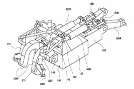
|
|
The or each front wheel (4) of the vehicle is
mounted on a stub axle (108F) at the lower end of a strut (173) articulated
in the central plane of the wheel to one end of an inverted U or J-shaped
suspension arm (106F) pivotally mounted on its other end on the vehicle
chassis and forming a parallelogram linkage with a wishbone member (171),
pivoted at (162) thereby providing constant trail for the wheel. To provide
increased stability, the vehicle can have two front wheels (4) and two rear
wheels (5) mounted on respective swing arms (106F) and (106R) respectively
and the swing arm movements can be restricted by stabilising brakes (121F)
and (1 |
||||||
|
Patent number |
Title of
the patent |
Publication
date |
Inventor
(s) |
Documents cited by the inventor (s) |
Cited documents in search report |
Other patents where this patent is cited in
search report |
Field of
application |
|
Structure of front wheel for two-wheeler |
2002-06-04 |
Eiji Nakahara |
None |
None |
WO2004045941 |
2F3T |
|
|
Figure |
Abstract |
||||||
|
|
PROBLEM TO BE SOLVED: To provide a structure of
front wheel for a two-wheeler which can ensure stability at running time on a
curve by a vehicle body itself. SOLUTION: First/second support arms 3, 4 are provided
respectively in the vertical upper/lower direction in a base shaft 2 on the
center line of a chassis 1, besides the first support arm 3 is provided with
a first shaft 31 in parallel to the base shaft 2, the second support arm 4 is
provided with a second shaft 41 in parallel to the base shaft 2, this
first/second shaft 31, 41 journals a suspension arm 5a, 5b, 6a, 6b protruded
respectively in both side directions of the chassis 1, to be provided in one
side two steps, its lower step suspension arms 5b, 6b are connected to a
shock absorber 7, and front wheel support members 8a, 8b journaling front
wheels 9a, 9b are supported by the upper step suspension arm 5a,; 6a and the
lower step suspension arms 5b, 6b, in addition a handle support shaft 11 is
connected to the base shaft 2. |
||||||
|
Patent number |
Title of
the patent |
Publication
date |
Inventor
(s) |
Documents cited by the inventor (s) |
Cited documents in search report |
Other patents where this patent is cited in
search report |
Field of application |
|
A laterally tilting three-wheeled vehicle |
2002-02-20 |
Marco Doveri |
WO9843872 (see 1F3T) ITPN15179B180 (Tartarini) |
DE19838328 |
WO2006134270 WO2006072971 WO2004011324 |
2F3T |
|
|
Figure |
Abstract |
||||||
|
|
The vehicle possesses two steering front wheels
(21A, 21 B) and a viscoelastic suspension system for said wheels such that
lateral tilting of the vehicle is accompanied by an equal tilting of the
steering axes ( |
||||||
|
Patent number |
Title of
the patent |
Publication
date |
Inventor
(s) |
Documents cited by the inventor (s) |
Cited documents in search report |
Other patents where this patent is cited in
search report |
Field of application |
|
Improvement in vehicles having two front rolling and
steering wheels and at least a rear driving wheel |
2001-12-06 |
Gaetano Cocco Andrea Raffaelli Leandro Scomazzon |
WO9941136 US4003443 US4887829 US5611555 (see 1F3T; EP0606191) WO972707 WO9843872 (see 1F3T) |
US4375293 WO9947372 AU1467183 GB2155410 |
FR2881395 WO2005058680 (see 2F4T) |
2F3T |
|
|
Figure |
Abstract |
||||||
|
|
Motor-vehicle having at least a rear driving wheel
and two front rolling and steering wheels connected to each other by a
linkage mechanism (15; 15bis) provided with a suspension system (19) that
comprises at least a pair of shock-absorbing struts (60A, 60B; 60C, 60D) and
rocking levers (61A, 61B; 61C, 61D) associated therewith. An interconnecting
latticework (14) extending along the median plane (PM) of the vehicle
supports the axis (A) of the pins (50, 51; 57, 58) of the rocking levers
(61A, 61B; 61C, 61D) so that it is caused to lie on the same median plane and
parallel to the axes (X, Y) of the fulcrum pins (52, 53, 54) of the cross
bars (20, 21, 22, 23) of the linkage mechanism (15). The rolling speed of the
front wheels can be varied. |
||||||
|
Patent number |
Title of
the patent |
Publication
date |
Inventor
(s) |
Documents cited by the inventor (s) |
Cited documents in search report |
Other patents where this patent is cited in
search report |
Field of
application |
|
Three-wheeled vehicle with two front steering wheels |
2001-11-21 |
Allessandro Bagnoli |
None |
DE1063473 DE29701408U US2493817 DE4323120 |
WO2006072971 EP1619097 WO2005058680 (see 2F4T) WO2005037637 |
2F3T |
|
|
Figure |
Abstract |
||||||
|
|
A three-wheeled vehicle (11) with two front steering
wheels, comprising a frame, an handlebar, a steering assembly, and front and rear
wheels, in which two front wheels (37) are provided supported by a
forecarriage (12) and a rear axle (13) , the forecarriage (12) and rear axle
(13) being articulated together in a hinge region (14), the rear axle (13)
pitching in a vertical plane with respect to the forecarriage (12), and there
being a shock absorber (15) set between the forecarriage (12) and the rear
axle (13), a steering column (19, 19a) connected to the handlebar (20), the
steering column (19, 19a) being housed and free to turn in a pair of steering
tubes or sleeves (18, 24), one being connected to the rear axle (13) and the
other to the forecarriage (12), one end (19a) of the steering column being
connected to a pair of articulated rods (39, 40); which are set in succession
and which control supports (38) bearing the front wheels (37), the supports
(38) being connected to opposite rods (33, 34) of an articulated
quadrilateral (31, 32, 33, 34) supported on the remaining two opposite rods
(31, 32) by two hinges (30, 35), which are both carried by the forecarriage
(12) . |
||||||
|
Patent number |
Title of
the patent |
Publication
date |
Inventor
(s) |
Documents cited by the inventor (s) |
Cited documents in search report |
Other patents where this patent is cited in
search report |
Field of
application |
|
Vehicle with variable guided pendular motion |
2000-10-19 |
Jean-Philippe Minot |
None |
US4993733 FR2752213 |
FR2858963 |
2F3T |
|
|
Figure |
Abstract |
||||||
|
|
The invention concerns a vehicle (1) comprising a
truck chassis (2) articulated about a rotation axis (ZZ') on a steering
assembly (3) including at least two drive wheels (4a, 4b), characterised in
that it comprises inclining means (MI) enabling the rotation axis (ZZ') to be
inclined. |
||||||
|
Patent number |
Title of
the patent |
Publication
date |
Inventor
(s) |
Documents cited by the inventor (s) |
Cited documents in search report |
Other patents where this patent is cited in
search report |
Field of
application |
|
Veicolo a ruote anteriori rollanti e sterzanti |
2000-09-04 |
Gaetano Cocco Andrea Raffaelli |
|
None |
None |
|
|
|
Figure |
Abstract |
||||||
|
Not
available |
Not available |
||||||
|
Patent number |
Title of
the patent |
Publication
date |
Inventor
(s) |
Documents cited by the inventor (s) |
Cited documents in search report |
Other patents where this patent is cited in
search report |
Field of
application |
|
A three-wheeled car frame capable of inclining when
handling a curve |
1999-08-19 |
Maurizio Ficcadenti |
None |
FR2522590 US5544906 |
EP1362779 (see 2F4T) GB2374327 |
1F3T; 2F3T |
|
|
Figure |
Abstract |
||||||
|
|
A car frame for three-wheeled vehicles having two
steering front wheels and one rear wheel comprising a rigid portion and a
trapezoidal portion capable of being deformed and allowing the centre of gravity
of the vehicle and the loads applied thereon to be shifted to the inside of
the curve which is being run across, the steering being controlled by a
suitable linkage and handle bar (1), and the side inclination being
controlled by the driver by shifting his body. The front wheels steer by
rotating about two respective axes (S, S') orthogonal to the axes of rotation
(AA', BB') of the respective wheels and lie is a vertical plane passing
through the centres of the front wheels. The trapezoidal portion capable of
being deformed is the front portion, such a deformation causing the front
wheels to incline together with the rear portion where the driver's seat is
located. |
||||||
|
Patent number |
Title of
the patent |
Publication
date |
Inventor
(s) |
Documents cited by the inventor (s) |
Cited documents in search report |
Other patents where this patent is cited in
search report |
Field of
application |
|
|
Motor vehicle with bottom sub-unit |
1999-03-10 |
Guenter Hoelzel Franz Maier |
DE3933417 |
DE6813513U EP0251906 (see 1F3T) US5641194 EP0298903 DE3933417 |
EP1894753 EP1862380 FR2818950 |
2F3T
|
|
Figure |
Abstract |
||||||
|
|
The floor of a vehicle is thicker, where the
occupants are located, with a deflecting angle (9) at the flooring (8). It is
angled downwards on the longitudinal center plane, where the vehicle (1)
tilts on a curve. The deflection angle is pitched at about 30 degrees to the
horizontal. |
||||||

|
Patent number |
Title of
the patent |
Publication
date |
Inventor
(s) |
Documents cited by the inventor (s) |
Cited documents in search report |
Other patents where this patent is cited in
search report |
Field of
application |
|
Three-wheel
motorcycle |
1999-01-29 |
Georgi Chervendinev |
? |
None |
None |
2F3T |
|
|
Figure |
Abstract |
||||||
|
|
The invention relates to a motorcycle having a
two-wheelfront bridge which is secured against any side inclination. It
hassmall overall dimensions enabling running in a bend with limitedto a minimum
side slipping of the front wheels. The three-wheelmotorcycle includes a rear
(11) and two front (12, 13) wheels andtwo stub axles (21, 22) in the front
part of which two king pins(24) and wheels (12 & 13) rest. Two parallel
lateral beams (31,32) are connected in a mobile way with their ends to the
ends ofthe two king pins (24), and in their central part they rest on
acentral cross-bar (33). Cross-bar (33) is connected to trame (1)two parallel
longitudinal beams (41, 42) the front ends of whichare pivotly connected to
it. The outer ends of lateral steeringlevers (57, 58) are connected in a
mobile way to the side steeringsections (26). An interlocking (61)
and limiting (71) mechanism are also designed. |
||||||
|
Patent number |
Title of
the patent |
Publication
date |
Inventor
(s) |
Documents cited by the inventor (s) |
Cited documents in search report |
Other patents where this patent is cited in
search report |
Field of
application |
|
US6250649 |
Multi-track curve tilting vehicle |
1998-11-05 |
Dieter Braun |
EP0528783 DE19608578 |
EP0426995 EP0153521 US4484648 DE1001602 US3909022 |
EP1799472 FR2872772 |
2F3T |
|
Figure |
Abstract |
||||||
|
|
The invention relates to a curve tilting vehicle,
wherein the control system for the tilting superstructure comprises an emergency
backup system which enables the vehicle to operate for at least a given
period of time if the normally effective main system breaks down. Three
superstructure positions are possible depending upon the lateral acceleration
of the vehicle: maximum left tilt, upright position, and maximum right tilt.
The emergency backup system is controlled by means of an inertia mass. |
||||||
|
Patent number |
Title of
the patent |
Publication
date |
Inventor
(s) |
Documents cited by the inventor (s) |
Cited documents in search report |
Other patents where this patent is cited in
search report |
Field of
application |
|
Non track bound, multi-tracked vehicle |
1997-07-03 |
Dieter Braun |
DD138632 US2231338 |
DD138632 US2231338 |
None |
2F3T |
|
|
Figure |
Abstract |
||||||
|
|
The vehicle comprises a steering gear which is
arranged between a superstructure-side hand steering wheel and the vehicle
steering wheels, which has a compensation gear for compensation of the reactions
of the tilting movements of the superstructure on the vehicle steering
wheels. An axle unit (5,6) which has a travel stool (5) rotatable relative to
the superstructure only around its pivot axis (4) of the tilting movements
and is immovable in other directions. The stool is rotatively adjustable
relative to the superstructure by a tilting position unit (10). Between the
hand steering wheel (7) and the travel stool-side steering gear parts a
planet gear (9) is arranged. |
||||||
|
Patent number |
Title of
the patent |
Publication
date |
Inventor
(s) |
Documents cited by the inventor (s) |
Cited documents in search report |
Other patents where this patent is cited in
search report |
Field of
application |
|
Vehicle with at least three wheels and a suspension
system |
1997-06-19 |
Romeo Muccio |
None |
DE1063473 EP0560670 GB2155411 FR2391892 DE822487 |
WO03018390 GB2374327 WO9941136 |
2F3T |
|
|
Figure |
Abstract |
||||||
|
|
A vehicle having at least three wheels (11) with a suspension
system comprising at least two arms (10) hinged at one end thereof to the
frame of the vehicle (1, 8, 16) and at the opposite end thereof to the hub of
the respective wheel, damping and elastic members (14) hinged to said arms
and to said frame of the vehicle; the arrangement of said arms on said frame
being such that it allows the latter to be inclined inwards of a curved
trajectory and in such a way that the sum of the resulting forces applied to
said frame always passes through, or at least nearby the centre of gravity
thereof (3). |
||||||
|
Patent number |
Title of
the patent |
Publication
date |
Inventor
(s) |
Documents cited by the inventor (s) |
Cited documents in search report |
Other patents where this patent is cited in
search report |
Field of
application |
|
Banking suspension |
1994-12-21 |
David Dovison |
None |
GB729190 GB2155411 EP0251906 (see 1F3T) US4484648 US4624469 |
EP1894753 WO2006129020 WO2006108997 WO2006003489 WO2005095195 WO2005058680 (see 2F4T) FR2858963 WO2004011324 WO0192084 EP1078844 WO9941136 |
1F3T ; 2F3T |
|
|
Figure |
Abstract |
||||||
|
|
A form of vehicular suspension which duplicates the
dynamic properities of a motor/pedal bikers suspension and which is also capable
of keeping the vehicle upright when it is moving slowly or is stationary is
achieved by having at least one pair of wheels 3 laterally disposed about the
vehicle's body 4 in conjunction with a mechanism connecting the wheel's
uprights and the body in such a manor as to allow them to rotate freely and
in unison about the wheel's contact points with the ground. Thus the machine
may be banked into corners like a bike. The vehicle's angle of lean is
controlled by use of wheel gyroscopic forces. At low speed and when
stationary the mechanism is locked in rotation relative to the body and thus
the vehicle becomes in effect a narrow car.; As the rider/driver does not
have to be able to touch the ground with his feet to stabilise the vehicle,
it may be fully enclosed, and therefore has the potential to be as safe as
car. |
||||||

|
Patent number |
Title of
the patent |
Publication
date |
Inventor
(s) |
Documents cited by the inventor (s) |
Cited documents in search report |
Other patents where this patent is cited in
search report |
Field of
application |
|
Front two-wheel type vehicle |
1993-06-08 |
Hiroshi Kamiya Naoyuki Saito |
? |
None |
DE102005055687 |
2F3T |
|
|
Figure |
Abstract |
||||||
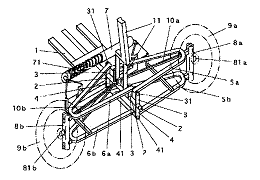
|
|
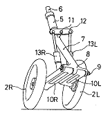
PURPOSE:To reduce the interval between the left and right
wheels and hold the sufficient cushion stroke, as for a front two-wheel type
vehicle. CONSTITUTION:Left and right swing arms 10L and 10R are pivotally
installed on a front arm 7 extending from a steering shaft 6, and front
wheels 2L and 2R are held at the rear edge. A balance lever 12 as motion
direction changing means is pivotally installed in the upper part of the
front arm, and cushion springs 13L and 13R are interposed between the swing
arms 10L and 10R and both the edges of the balance lever 12 |
||||||
|
Patent number |
Title of
the patent |
Publication
date |
Inventor
(s) |
Documents cited by the inventor (s) |
Cited documents in search report |
Other patents where this patent is cited in
search report |
Field of
application |
|
Three-wheeled vehicle |
1987-10-06 |
Wolfgang Trautwein |
DE2707562 GB1561253 JP1176544 IT48171 TWUM9367 |
US4020914 IT501464 GB155025 GB359089 |
US2005139433 US2002030344 US2002148664 GB2338218 US5236060 |
2F3T |
|
|
Figure |
Abstract |
||||||
|
|
A vehicle with three wheels includes a single rear
driven wheel and two front steerable wheels. The front wheels are supported
by cross members in a parallelogram mechanism carried by the frame of the
vehicle. A platform is connected to the frame and extends rearwardly of the
cross members on both sides of the lower cross member. A U-shaped center
stand is pivotally connected to the platform an axis extending
perpendicularly to the longitudinal axis of the vehicle. The center stand in
its deployed supporting position also engages the vehicle frame for keeping
the vehicle upright. |
||||||
|
Patent number |
Title of
the patent |
Publication
date |
Inventor
(s) |
Documents cited by the inventor (s) |
Cited documents in search report |
Other patents where this patent is cited in
search report |
Field of
application |
|
Self stabilizing
cambering vehicle |
1987-05-21 |
Phillip Ronald James |
None |
US4550926 GB2155411 DE2455183 DE452792 |
WO2005095195 WO2004098915 EP1145879 GB2374327 WO9003298 |
2F3T |
|
|
Figure |
Abstract |
||||||
|
|
Three or four wheeled vehicle which leans into
corners so as to remain stable even when the vehicle has a narrow track. The
steering mechanism is such that leaning of the vehicle to either respective
side of the vertical causes the front steering wheels (10) to turn in the
same steering direction, e.g. a lean to the left causes an anticlockwise,
when viewed from above, turning of the front wheels (10). The front wheels
(10) can be supported on a parallelogram linkage system (17, 18) so that the
steering axis (16) of the wheels (10) remain parallel with the vehicle body
as the vehicle leans.; Steering can be controlled through a steering wheel
(14) which, disregarding the influence of body lean, turns the front wheels
(10) in a steering direction relative to the turn of the steering wheel which
is opposite in sense, e.g. an anticlockwise turn of the steering wheel (14)
produces a clockwise turn, when viewed from above, of the front wheels (10).
In order to produce a predetermined steering characteristic the ratio between
the angle of lean of the vehicle and the responsive angle of turn of the
front wheels (10) varies with the forward velocity of the vehicle. |
||||||
|
Patent number |
Title of
the patent |
Publication
date |
Inventor
(s) |
Documents cited by the inventor (s) |
Cited documents in search report |
Other patents where this patent is cited in
search report |
Field of
application |
|
Body banking suspension apparatus for a vehicle |
1986-12-30 |
Masao Ogawa Kenji Honma Harayasu Fujita |
JP5425033 |
US2852268 US4546997 |
US7185902 US2005248116 DE10358522 WO03057517 WO03059663 US6109621 US5765846 WO9615006 US4903857 (Human powered) US4840393 US4717164 (human powered) |
2F3T 2F4T |
|
|
Figure |
Abstract |
||||||
|
|
A suspension apparatus for a vehicle adapted to
decline the body and/or the wheels toward the turning center side according
to the steering operation when the vehicle makes a turn. In this suspension
apparatus, the end portion of a suspension spring at the vehicle body side or
the end portion of an upper arm at the vehicle body side are secured to a
movable member associated with a steering operation member for movement. In
the vehicle equipped with this suspension apparatus, driver can enjoy the
similar steering sense or feeling as a motorcycle. |
||||||
|
Patent number |
Title of
the patent |
Publication
date |
Inventor
(s) |
Documents cited by the inventor (s) |
Cited documents in search report |
Other patents where this patent is cited in
search report |
Field of
application |
|
Three-wheeled vehicle with controlled wheel and body
lean |
1986-11-25 |
Maurice Bourne Jr |
US627523 US3746118 US4020914 US4351410 |
US627523 US2434759 US3746118 US3934668 US4020914 |
US2008217085 US2006017307 US2003111279 US2002190494 GB2382334 GB2374327 US2002104696 US6367824 US5927424 US5762351 (Human powered) US4941673 US4903857 (Human powered) |
2F3T |
|
|
Figure |
Abstract |
||||||
|
|
The specification discloses a three-wheeled vehicle
with a steering mechanism configured and arranged to provide
driver-controlled wheel and body lean as the vehicle is making a turn. A
cradle is rotatably mounted at the front of the vehicle for rotation about an
axis generally longitudinal relative to the body. An axle connected to the
cradle is perpendicular to the axis of rotation of the cradle and a spindle
is pivotally connected to each end of the axle. A wheel is rotatably mounted
on each spindle. A tie rod pivotally connected at its ends to the spindles is
held in a selected position about the axis of the axle by a tie rod linkage.
A coupler rotatably connects the linkage to the body. The linkage is also
rotatably connected to the axle for rotation about an axis perpendicular to
the axle to move the tie rod laterally.; When the linkage is disposed to hold
the tie rod forward of the axle, a force causing rotation of the movement of
the tie rod laterally produces a conventional turning effect. When the linkage
is disposed to hold the tie rod vertically above the axle, movement of the
tie rod laterally causes the body to rotate about its connection to the
cradle by virtue of the coupler, and causes the wheels to lean, producing
simultaneous wheel and body lean. Locating the linkage to hold the tie rod in
an intermediate position produces a combined leaning and turning effect. |
||||||
|
Patent number |
Title of
the patent |
Publication
date |
Inventor
(s) |
Documents cited by the inventor (s) |
Cited documents in search report |
Other patents where this patent is cited in
search report |
Field of
application |
|
Vehicle tilting
device |
1986-10-13 |
Yoshinori Kawashima Masao Ogawa Haruyasu Fujita |
� |
None |
US5040812 |
2F3T 2F4T |
|
|
Figure |
Abstract |
||||||
|
|
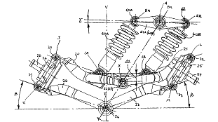
PURPOSE:To enhance the turnability of a vehicle
having at least one set of left and right wheels in pair, by arranging such that
the vehicle automatically tilts toward the center of turn of the vehicle in
accordance with the steering operation of the vehicle so that control feeling
similar to a motor-cycle may be obtained. CONSTITUTION:When a steering wheel
20 is rotated in the direction (a) to turn a vehicle to, for example, the
right during running of the vehicle, a slide shaft 13 is moved leftward
through a pinion 18 to deflect a front wheel 1 rightward.; Further,
simultaneously hydraulic pressure is fed into a cylinder 23 in a suspension
device 14 on the left side (right side in the figure) through a fluid
change-over device (rotary valve) which is not shown and which is operated in
association with the rotation of the steering wheel while hydraulic oil is
discharged from a cylinder 23 in a right side suspension device 14. With this
arrangement, the left side cylinder 23 is moved upward while the right side
cylinder 23 is moved downward, thereby a vehicle body 2 is inclined rightward
or toward the center of turn through a lower arm 4 and an upper arm 6. |
||||||
|
Patent number |
Title of
the patent |
Publication
date |
Inventor
(s) |
Documents cited by the inventor (s) |
Cited documents in search report |
Other patents where this patent is cited in
search report |
Field of application |
|
Vehicle steering and suspension system |
1985-10-15 |
Eugene Smyers |
US1283942 US2029735 US2053294 US2260102 (see
2F4T; FR837939) US2493817 US3447623 US3746118 US3964563 US4020914 US4072325 |
US1283942 US2029753 US2045562 US2053294 US2260102 (see
2F4T; FR837939) |
US7343997 US2007131474 US2007126199 WO2006016311 WO2005075278 WO2005051712 EP1506917 US2005248116 US2004188167 EP1431097 US2005040619 EP1403171 EP1378427 US6663122 US2002190494 DE10224289 US2002093152 US2003164603 US2003122336 US2002148664 US6378882 US6435522 US6367824 US6250649 (see WO9849023) US6267387 WO9912795 US6170838 US6113119 US6105986 FR2745757 (Automotive patent) US5836598 US5762351 (Human powered) US5580089 US5094472 US4998596 US4938494 US4752079 US4600216 US4632413 |
2F3T |
|
|
Figure |
Abstract |
||||||
|
|
A three-wheeled vehicle steering and suspension
system including two support assemblies for two opposed front wheels
pivotably mounted at opposite sides of the vehicle frame and operatively connected
by a hydraulic cylinder arrangement actuated by the vehicle steering linkage
for inducing opposed pivotal movement of the support assemblies during
vehicle turning to cause leaning of the vehicle in the direction of turning.
A biasing arrangement provides the operative connection between the hydraulic
cylinder and the support assemblies for transmitting lean-actuating
reciprocatory movement of the hydraulic cylinder to the support assemblies
while yieldably permitting independent pivotal movements thereof.; The
biasing arrangement may include respective torsion bars fixed at respective
ends thereof to the opposite ends of the hydraulic cylinder and at the other
respective ends thereof to the support assemblies, the torsion bars being
correspondingly rotated by the hydraulic cylinder to actuate the opposed
pivotal movement of the support assemblies. A shock absorber is mounted on
each torsion bar and extends therefrom to the respective support assembly for
dampening independent movements thereof without creating resistance to
rotation of the torsion bar by the hydraulic cylinder. Alternatively, the
shock absorber may provide the biasing connection between the hydraulic
cylinder and the support assemblies. An electro-hydraulic system actuates
reciprocation of the hydraulic cylinder in direct relation to the degree of
vehicle turning and to the vehicle speed. |
||||||
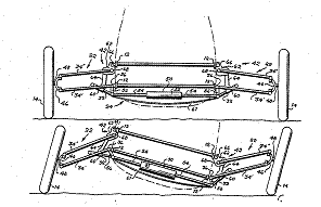
|
Patent number |
Title of
the patent |
Publication
date |
Inventor
(s) |
Documents cited by the inventor (s) |
Cited documents in search report |
Other patents where this patent is cited in
search report |
Field of
application |
|
Suspension apparatus
for vehicle |
1985-09-25 |
Takahisa Suzuki Masao Ogawa Kenji Honma Harayasu Fujita |
JP5425033 |
GB2039834 GB869984 GB836298 GB796683 GB720551 |
GB2444250 (see 1F3T; 2F4T) EP1799472 WO0192084 US6109621 US5927424 WO9534459 (see 1F3T) |
2F3T 2F4T |
|
|
Figure |
Abstract |
||||||
|
|
Telescopic members (241, 242) which are expanded and
contracted by means of a fluid pressure controlled by a steering mechanism
(20) are integrally connected to suspension springs (141, 142). When a
vehicle makes a turn, the body is caused to decline toward the turning center
side due to the telescopic movement of the telescopic members according to
the steering operation. The fluid pressure may be fed from a hydraulic
cylinder (26) including a piston (27) associated for movement with the
steering mechanism. Alternatively, fluid pressurized by a pump may be fed
through a controlling valve which is actuated in response to the steering
mechanism. At a time when the vehicle makes a turn, a satisfactory steering
sense similar to a motorcycle can be obtained. |
||||||
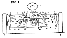
|
Patent number |
Title of
the patent |
Publication
date |
Inventor
(s) |
Documents cited by the inventor (s) |
Cited documents in search report |
Other patents where this patent is cited in
search report |
Field of
application |
|
Vehicle for terrestrial use, particularly a tricycle |
1984-08-16 |
Jan Cornelis Geerlof |
None |
US2696387 CA981717 US1817478 US2150199 FR1183913 |
WO9806620 US4660853 EP0153521 |
2F3T |
|
|
Figure |
Abstract |
||||||
|
|
A vehicle for terrestrial use is equipped with three
distantly arranged supporting means (3, 4) for forward movement. Two of these
supporting means (3) being displaceable in unison by means of a common
steering device (12, 13, 14) and are each pivotally arranged on an extended
supporting arm (5) at the front part of the vehicle. The third supporting
means (4) being of a traditional nature of support only and each relevant
extended pivot (9) of the said two supporting means (3) lying in a common
plane which intersects the plane containing the said vehicle's two supporting
contact surfaces and the points of support, each extended pivot axis (16)
taking a rearward angle of inclination with respect to the vertical plane
through the longitudinal axis of the vehicle.; The points of intersection
(19) of each pivot axis (16) with the horizontal plane of support lying in an
outward direction perpendicular to the vehicle's longitudinal axis and
sidewardly and outwardly away from each of said points of contact whereby the
arrangement being suchlike that while the vehicle traversing a curved path,
the vehicle's frame is subjected to a "pendulum" action inthe
direction of turning. This "pendulum" actions causes a relative
different movement while progressively turning the vehicle's supporting means
located at the inner part of the curve moving more in a forward direction,
whereas the supporting means located at the outer part of the curve being
more retracted with respect to the said forward movement and vice versa. |
||||||
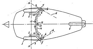
|
Patent number |
Title of
the patent |
Publication
date |
Inventor
(s) |
Documents cited by the inventor (s) |
Cited documents in search report |
Other patents where this patent is cited in
search report |
Field of
application |
|
Front suspension and steering system for cycles and
motorcycles having two interdependent points of support on the ground |
1983-03-01 |
Francisco Solbes |
None |
US1993458 US2217818 US2299241 US2563370 US3309097 |
US7543829 WO2006134270 WO2006072971 US2004160030 US2004140645 WO0187698 WO0192084 US6367824 WO9718017 US5762351 (Human powered) US4887829 US4740004 |
2F3T |
|
|
Figure |
Abstract |
||||||
|
|
The present invention relates to a suspension and
steering system enabling the road holding, braking efficiency and safety of
presently known cycles and motorcycles of all types, on wheels or on skis, to
be increased, while maintaining their capacity to bank when cornering, their
handling ability and small dimensions. This system is composed of the
combination of two sub-systems:-the suspension sub-system intended to carry
two wheels or two skis, comprises: (a) a mechanism composed of two forks, two
pairs of guide shafts, and two supports. The forks move over the guide shafts
which are fixed to the supports; (b) a mechanism composed of a support, a
rocking arm and a handle bar.; This arm rocks on the axis of the support and
allows the interdependent displacements of the forks; -the steering
sub-system is intended on the one hand to carry the above mentioned
mechanisms of the suspension sub-system and on the other hand to be
articulated on the frame at the steering column and the reinforcing arm. It
is composed of the devices which form the central shaft. |
||||||
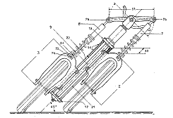
|
Patent number |
Title of
the patent |
Publication
date |
Inventor
(s) |
Documents cited by the inventor (s) |
Cited documents in search report |
Other patents where this patent is cited in
search report |
Field of
application |
|
Tricycle with two fore wheels |
1982-11-23 |
Nobuyuki Kanno Toshiyuki Sato |
US3572456 US2493817 US3746118 |
US2152938 US2493817 US2791440 US2978255 US3572456 |
US2007126199 US2007007745 WO2006072971 EP1506917 WO2005002957 US2004227321 EP1431097 US2004035628 US2004040770 US2002190494 US6286846 US4903857 (Human powered) US4714126 US4787470 US4717164 (human powered) US4634137 FR2562479 WO8400338 US4469344 US4487282 |
2F3T |
|
|
Figure |
Abstract |
||||||
|
|
A tricycle having two spaced fore wheels and a
single rear wheel connected to a frame structure. The fore wheels are
connected to the frame by a longitudinally extending shaft. A double wishbone
suspension comprised of a pair of upper arms and a pair of lower arms
connected by vertical links at their outer ends join the fore wheels to the
frame and longitudinal shaft. The upper arms are pivotally connected to the
frame while the lower arms are pivotally and separately connected to the
longitudinal shaft by a shock absorbing cushion. |
||||||
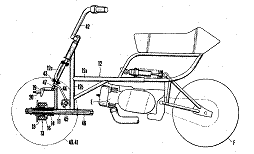
|
Patent number |
Title of
the patent |
Publication
date |
Inventor
(s) |
Documents cited by the inventor (s) |
Cited documents in search report |
Other patents where this patent is cited in
search report |
Field of application |
|
Self-balancing
wheeled vehicle |
1982-01-22 |
Ray Townsend |
None |
GB1561253 FR2284510 US3746118 EP0020835 (see 1F1T) US2684254 US3820809 US3958814 US4020914 |
WO03018390 US6109621 FR2667041 EP0251906 (see 1F3T) FR2534869 US7343997 ES2284383 WO2006072971 US2005012291 US2004140645 GB2396308 US2002190494 WO0187698 DE10105743 US5967529 US5765846 US5762351 (Human powered) ES2089967 US5236060 US4903857 (Human powered) US4903790 US4740004 US4717164 (human powered) US4625825 US4662468 US4624469 US4634137 US4469344 |
2F3T |
|
|
Figure |
Abstract |
||||||
|
|
A wheeled vehicle includes a vehicle frame having at
least one wheel at one end of the frame and a hinged parallelogram frame mounted
on the other end of the vehicle frame and having a pair of spaced wheels
mounted on opposite sides thereof. The parallelogram frame will pivot
laterally in first or second opposite lateral directions when the frame leans
laterally away from a position of equilibrium in the first or second lateral
direction. A sensing device is connected to the vehicle frame and a power
source is connected to the sensing means and parallelogram frame whereby
initial leaning movement of the parallelogram frame in one direction (caused
by conditions of unequilibrium) will cause the sensing device and power
source to pivot the parallelogram frame in the opposite direction thereby to
laterally pivot the vehicle frame to a position of equilibrium.; The sensing
device may be a lever pivotally connected to the vehicle frame and the power
source may include a pair of extensible and retractable cylinder units for
connecting opposite ends of the sensor lever to opposite sides of the
parallelogram frame. |
||||||
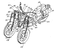
|
Patent number |
Title of
the patent |
Publication
date |
Inventor
(s) |
Documents cited by the inventor (s) |
Cited documents in search report |
Other patents where this patent is cited in
search report |
Field of
application |
|
Ultra Narrow enclosed motor vehicles |
1981-01-22 |
Edmund Jephcott |
None |
US4065144 US4126322 US4368796 BE548491 FR817173 FR2243103 GB1149079 FR1158922 US4064957 FR2338836 US4020914 US4003443 |
WO9406642 US4621442 US4621837 GB2450740 (see 1F3T) US2007126199 US2006123763 WO2005030559 US2003184071 WO9911507 US6015022 WO9849023 US5343973 US4998596 US4944360 US4919225 |
1F1T; 1F3T; 2F3T |
|
|
Figure |
Abstract |
||||||
|
|
A narrow enclosed motor vehicle has a chassis
supported by road-running wheels and a body structure for at least one person
mounted so as to be inclinable relative to the median plane of the vehicle
and at least a part of the chassis structure, inclination being controlled by
driver-operated pedals mounted to the inclinable section of the vehicle and
so connected that depression of either pedal causes the vehicle body to tilt
towards the same side of the median plane of the vehicle as the depressed
pedal. |
||||||
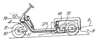
|
Patent number |
Title of
the patent |
Publication
date |
Inventor
(s) |
Documents cited by the inventor (s) |
Cited documents in search report |
Other patents where this patent is cited in
search report |
Field of
application |
|
Threewheeled vehicle |
1980-02-13 |
Wolfgang Trautwein |
DE1063473 |
None |
GB2438268 FR2841209 WO02098722 (see FR2825672, 1F1T) GB2382334 GB2203104 US4662468 FR2573024 FR2486899 |
2F3T |
|
|
Figure |
Abstract |
||||||
|
None |
None |
||||||
|
Patent number |
Title of
the patent |
Publication
date |
Inventor
(s) |
Documents cited by the inventor (s) |
Cited documents in search report |
Other patents where this patent is cited in
search report |
Field of
application |
|
Vehicle suspension system including wheel-tilting
mechanism |
1979-06-26 |
Ted Blaine |
US2652263 |
US1556531 US2206970 US2652263 US2689747 US2852268 |
EP1894753 US2007012015 US2003106297 US2002070509 US2001028154 US6244025 US6460318 EP0878378 EP1125828 US5306034 US5197755 US4973070 US4928984 US4911466 EP0319391 US4650213 US4659095 US4752079 US4657271 FR2562479 US4546997 US4377215 US4373743 US4294466 |
2F3T |
|
|
Figure |
Abstract |
||||||
|
|
A vehicle suspension system associated with a pair
of laterally spaced, steerable wheels includes novel wheel-control mechanism operable
in response to steering of the vehicle during a turn thereof for tilting the
outside wheel at a greater angle than the inside wheel in the direction of
the turn in order to automatically compensate for the effects of lateral
forces acting on the wheels which tend to be greater on the wheel tracking
the outside path of the turn compared with those forces acting on the wheel
tracking the inside path due to the lateral shifting of the vehicle's weight
as a result of body roll or the like. |
||||||
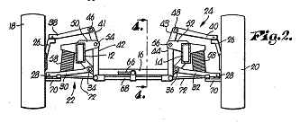
|
Patent number |
Title of
the patent |
Publication
date |
Inventor
(s) |
Documents cited by the inventor (s) |
Cited documents in search report |
Other patents where this patent is cited in
search report |
Field of
application |
|
Stabilized
three-wheeled vehicle |
1978-05-09 |
Wolfgang Trautwein |
US4020914 DE1063473 |
US2920636 US3561778 US3572456 US3583507 US3746118 |
US2007176384 US2007126199 US7143853 WO2004011324 US2004094346 WO03057549 US2003111279 GB2374327 US5611555 (see 1F3T; EP0606191) US5236060 US4998596 US4903857 (Human powered) US4863183 US4714126 US4699234 US4740004 US4624469 US4697663 US4634137 US4546997 USRE32031 US4477097 US4469344 US4368795 DE3040740 US4325565 (see 1F1T) US4277078 |
2F3T |
|
|
Figure |
Abstract |
||||||
|
|
A three-wheeled motorcycle in which two front wheels
are interconnected with a conventional motorcycle frame by a parallelogram
configured coupling assembly utilizing a pair of cross members pivotally
connecting hubs of the front wheels and pivotally connected to the frame.
Foot resting platforms are positioned on either side of the motorcycle, being
fixedly connected to one of the cross members in the front which is pivotally
connected to the motorcycle frame. |
||||||
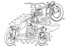
|
Patent number |
Title of
the patent |
Publication
date |
Inventor
(s) |
Documents cited by the inventor (s) |
Cited documents in search report |
Other patents where this patent is cited in
search report |
Field of
application |
|
Pendulum stabilized
ground vehicles |
1978-02-07 |
Donald Ray Bright Jerd Bright |
None |
US2623758 US3601213 US3820809 |
WO2007041095 US2005012291 EP1378428 DE10224289 US6378882 US6250649 (see WO9849023) DE19824576 DE19716506 DE19524802 DE19513649 US4903857 (Human powered) US4909538 US4634137 US4546997 FR2534869 DE3128371 EP0005214 |
2F3T |
|
|
Figure |
Abstract |
||||||
|
|
A device for automatically stabilizing moving ground
vehicles against the effects of transverse acceleration forces and roll moments,
due to turning maneuvers, by means of an on-board pendulum, suspended from a
stable platform, part of the vehicle, and intercoupled to pivotally supported
vehicle ground wheels, acting so as to incline the planes of rotation of the
pivotally supported ground wheels of the vehicle to the angle of the vector
resultant of the gravitational force component acting on the pendulum and the
transverse acceleration force component acting on the pendulum; the device
thereby provides, within the design maximum angle of inclination of the
ground wheels and the adhesion capability of the tires on the roadbed,
essentially complete stabilization of the turning vehicle.; The stabilizing
effect is that the angle of the force vector resultant acting on the vehicle will
nominally be that of the planes of rotation of the ground vehicle wheels,
excepting small steering and suspension system deviations that may act on the
steerable ground wheels or wheel. The vehicle is designed such that any
transverse forces acting on the vehicle automatically cause the vehicle to
lean, bank, or rotate about the longitudinal axis, much as a conventional
two-wheeled motorcycle leans on a turn, thereby establishing the necessary
angle of inclination required to balance the gravitational forces present and
the inertial forces generated by the turning maneuvers. |
||||||
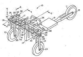
|
Patent number |
Title of
the patent |
Publication
date |
Inventor
(s) |
Documents cited by the inventor (s) |
Cited documents in search report |
Other patents where this patent is cited in
search report |
Field of
application |
|
Stabilized
three-wheeled vehicle |
1977-05-03 |
Wolfgang Trautwein |
DE1063473 |
FR544720 FR1158922 DE1063473 IT517430 IT543232 |
US7152868 US2005167174 US2005012291 EP1378428 US6663122 US2002148664 US6378882 WO0142077 US5762351 (Human powered) US5513865 US5431243 US5330214 US5236060 US5169166 US4944360 US4903857 (Human powered) US4909538 US4919225 US4662468 US4624469 US4697663 US4600216 FR2559103 US4546997 FR2534869 US4484648 US4351410 US4336964 US4313517 |
2F3T |
|
|
Figure |
Abstract |
||||||
|
|
A three-wheeled motorcycle in which two front wheels
are interconnected with a conventional motorcycle frame by a parallelogram
configured coupling assembly utilizing a pair of cross members pivotally
connecting hubs of the front wheels and pivotally connected to the frame.
Foot resting platforms are positioned on either side of the motorcycle, being
fixedly connected to one of the cross members in the front and pivotally
connected to the motorcycle frame at the rear. |
||||||
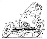
|
Patent number |
Title of
the patent |
Publication
date |
Inventor
(s) |
Documents cited by the inventor (s) |
Cited documents in search report |
Other patents where this patent is cited in
search report |
Field of
application |
|
Vehicle banking
mechanism |
1939-04-04 |
Edward Welch |
None |
None |
US2007085294 US2006017240 US2005258614 US2004040770 WO03078185 US2002093152 US2001028154 US6406036 FR2772308 US5040812 US4974863 US4550926 US4277085 US4133554 US4065144 US3746118 US3459438 US3089710 US2978255 US2850290 US2960349 US2739823 US2689747 US2676031 US2580559 US2576686 |
2F3T |
|
|
Figure |
Abstract |
||||||
|
|
None |
||||||