|
1900-1909 |
1910-1919 |
1920-1924 |
1925-1929 |
1930-1934 |
1935-1939 |
1945-1949 |
1950-1954 |
1955-1959 |
|
|
|
|
|
|
|
|
|
|
|
|
|
1960 |
1961 |
1962 |
1963 |
1964 |
1965 |
1967 |
1969 |
||
|
|
|
|
|
|
|
|
|
|
|
|
1970 |
1971 |
1972 |
1973 |
1974 |
1975 |
1977 |
1979 |
||
|
|
|
|
|
|
|
|
|
|
|
|
1980 |
1981 |
1982 |
1983 |
1984 |
1985 |
1987 |
1989 |
||
|
|
|
|
|
|
|
|
|
||
|
1990 |
1991 |
1992 |
1993 |
1994 |
1995 |
1997 |
1999 |
||
|
|
|
|
|
|
|
|
|
|
|
|
2000 |
2001 |
2002 |
2003 |
2004 |
2005 |
2007 |
2009 |
||
|
|
|
|
|||||||
|
2010 |
|
|
|
|
|
|
|
|
|
|
|
|
|
|
|
|
|
|
|
|
Patent number |
Title of
the patent |
Publication
date |
Inventor
(s) |
Documents cited by the inventor (s) |
Cited documents in search report |
Other patents where this patent is cited in
search report |
Field of
application |
|
CA2645252 US2010127471 |
Wheeled tilting
apparatus |
2010-05-26 |
Dennis Gazarek |
None |
None |
None |
2F4T |
|
Figure |
Abstract |
||||||
|
|
The apparatus has two tilting wheels which, when
attached to a two-wheeled vehicle such as a motorcycle or a scooter, allows
the vehicle to tilt into a curve notwithstanding the addition of the two wheels.
The apparatus includes a frame, a pair of wheel supports and a pair of wheels
each rotatable about a separate wheel support. A pair of links interconnect
the frame with the wheel supports. The apparatus includes a rocker pivotally
connected to the frame and a pair of transverse arms each pivotal about a
separate wheel support and the rocker. Each transverse arm has a coil spring
for biasing the wheel support and rocker apart. When a vehicle equipped with
the apparatus rounds a curve, the frame tilts in the direction of the curve
with like tilting of the wheels of the apparatus. |
||||||
|
Patent number |
Title of
the patent |
Publication
date |
Inventor
(s) |
Documents cited by the inventor (s) |
Cited documents in search report |
Other patents where this patent is cited in
search report |
Field of
application |
|
Rotating mechanical transmission for a tilting
system of the wheels of a vehicle with three or four wheels |
2010-02-11 |
Luciano Marabese |
WO9727071 (see 1F3T) |
FR2841870 (see 1F3T) EP1282551 (see 1F1T; WO0187689) WO9727071 (see 1F3T) |
None |
1F3T; 2F4T |
|
|
Figure |
Abstract |
||||||
|
|
The present invention relates to a wheel tilting
system for vehicles with three or more wheels in which at least two wheels
are set alongside on the same axle. The wheel tilting system according to the
present invention comprises at least one oscillating arm (2) for each wheel
and at least one mechanical transmission (3, 3a, 3b, 4) adapted to connect
said arms (2) to one another and adapted to transmit the motion of
oscillation of said arms (2) into the motion of rotation of a connection rod
(3) about its axis. The tilting system according to the present invention it
particularly simple to be implemented and thus cost-effective as well as
operatively reliable. Furthermore, such a system have very small dimensions
and light weight. |
||||||
|
Patent number |
Title of
the patent |
Publication
date |
Inventor
(s) |
Documents cited by the inventor (s) |
Cited documents in search report |
Other patents where this patent is cited in
search report |
Field of
application |
|
FR2931395 |
Suspension device for a moving object |
2009-12-17 |
Olivier Antenat |
W02006130007 |
EP1213043 WO9718017 EP1484239 (see 2F3T) EP1227966 EP1391374 |
None |
2F3T; 2F4T |
|
Figure |
Abstract |
||||||
|
|
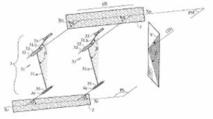
The invention relates to a device comprising a base
(1) for receiving a load, connected to two side supporting elements (2)
supported by the medium and formed by two hinged assemblies (3) including a
swivel lever (31) with two arms (31a, b) forming therebetween an obtuse angle
(ss) other than 180 DEG , said arms being connected to a central pivot (32,
33) and each arm terminating in a side pivot (35, 36). The central pivot (32,
33) is connected to the base (1) and the side pivots are each connected to a
side supporting element (35, 36). The feet of the pivots (33) are positioned
on a straight baseline (XoXo) of the base (1) and the two homologous side
pivots (36) are positioned on an auxiliary line (X1X1) of the side supporting
element (2). The lines (XoXo) and (X1X1) are parallel to a direction d and
the axes of the pivots are parallel and form an angle (a) other than 90 DEG
with said direction d. The optimum angles for the suspension device are a =
32.79 DEG , ss = 149.70 DEG . |
||||||
|
Patent number |
Title of
the patent |
Publication
date |
Inventor
(s) |
Documents cited by the inventor (s) |
Cited documents in search report |
Other patents where this patent is cited in
search report |
Field of
application |
|
Motor vehicle with controlled inclination |
2009-09-03 |
Daniel Moulene Thierry Moulene |
None |
FR2872773 (see WO2006003489) DE19738826 (automotive patent) US2006170171 (see 2F3T; WO2004056645) WO9727071 (see 1F3T) FR2646379 (see 1F3T) |
None |
1F3T ; 2F4T |
|
|
Figure |
Abstract |
||||||
|
|
The motor vehicle of the invention is provided with
at least three wheels (3) and includes a driving cab (2) capable of
accommodating a single person in the width direction. The motor vehicle
comprises a bend-balancing means that acts by the inclination of at least the
portion of the chassis (1) that bears the driving cab. According to the
invention, the vehicle is also provided with speed, acceleration and/or
inclination sensors, and the balancing means are automatically controlled
when the information supplied by the sensors is lower than a main
predetermined threshold. The invention also provides that the automatic
control of the balancing means is deactivated when the information provided
by the sensors is higher than said main threshold. |
||||||
|
Patent number |
Title of
the patent |
Publication
date |
Inventor
(s) |
Documents cited by the inventor (s) |
Cited documents in search report |
Other patents where this patent is cited in
search report |
Field of
application |
|
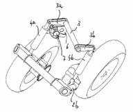
Device for allowing quadricycle type vehicle to take
angle in turns, has wheels fixed on articulated arms, where wheels take angle
such that vehicle/driver tilts at interior of turn, while ensuring free
access to different controls |
2009-07-31 |
Olivier Fery |
None |
None |
None |
2F4T |
|
|
Figure |
Abstract |
||||||
|
|
The device has a frame (2) installed on a lateral
tilting axis (3) and fixed to a chassis (13). Perpendicular axles (4) are
connected by the chassis. Left and right articulated arms (5) are mounted on
a ball bearing, and wheels (1) are fixed on the arms. The left arms are
pivoted towards top, and the right arms are pivoted towards bottom, when the
frame is tilted at the left. The wheels take an angle such that a
vehicle/driver tilts at the interior of the turn, while ensuring free access
to different controls. |
||||||
|
Patent number |
Title of
the patent |
Publication
date |
Inventor
(s) |
Documents cited by the inventor (s) |
Cited documents in search report |
Other patents where this patent is cited in search
report |
Field of
application |
|
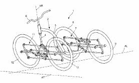
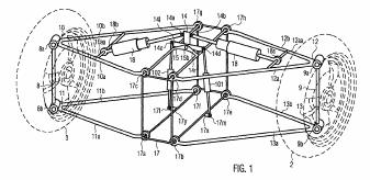
WO2009074752 |
Terrestrial vehicle for e.g. three- |
2009-04-03 |
Guillaume Demolliens |
None |
GB2279047 (see 1F3T; 2F3T) DE1063473 EP1155950 (see 2F3T) WO9721583 (see 1F3T; 2F3T) |
None |
2F3T ; 2F4T |
|
Figure |
Abstract |
||||||
|
|
The vehicle has a frame (2) connected to right and left
rear wheels (8, 9) and right and left front wheels (12, 13) via deformable
parallelogram type rear and front variable geometry axles (7, 11), where the
wheels are transversely spaced on both sides of an longitudinal axis (AL).
The axles have a connection unit that inclines the wheels while moving the
wheels along the opposed horizontal directions, by the inclination of the
frame around the axis. |
||||||
|
Patent number |
Title of
the patent |
Publication
date |
Inventor
(s) |
Documents cited by the inventor (s) |
Cited documents in search report |
Other patents where this patent is cited in
search report |
Field of
application |
|
Suspension system |
2008-06-05 |
Nicholas Richard
Shotter |
EP01998472 EP03253106 |
US2006192361 US2004113377 DE10349655 JP61278412 WO0244008 EP1362779 |
None |
1F3T ; 2F4T |
|
|
Figure |
Abstract |
||||||
|
|
A suspension system for a leanable vehicle having a
pair of laterally spaced wheels (1, 2) with hydraulic dampers (17, 18) associated
with the wheels and control means selectively operable to operate a
changeover valve (25) to cause the dampers (17, 18) to operate either
independently or simultaneously to alter the operating characteristics of the
suspension. In one position of a changeover valve (25), chambers above and
below pistons (17b and 18b) are interconnected for each damper to allow
normal tilting of the vehicle while still permitting suspension movements. In
a second position of the changeover valve (25), the chamber above piston
(17b) is interconnected with the chamber below piston (18b) and the chamber
below piston (17b) is interconnected with the chamber above piston (18b),
thereby preventing further tilting of the vehicle, whilst maintaining full
suspension movement. |
||||||
|
Patent number |
Title of the patent |
Publication date |
Inventor (s) |
Documents
cited by the inventor (s) |
Cited
documents in search report |
Other
patents where this patent is cited in search report |
Field of application |
|
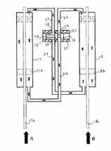
Hydraulic damper system for a leanable vehicle |
2008-06-04 |
Nicholas Richard
Shotter |
EP01998472 EP03253106 |
GB2155410 DE4035128 EP1362779 WO9727071 (see 1F3T) |
None |
1F3T ; 2F4T |
|
|
Figure |
Abstract |
||||||
|
|
A suspension system for a leanable vehicle, such as
a motorcycle, has a pair of laterally spaced wheels 1 and 2 with hydraulic
dampers 18 and 19 associated with the wheels 1 and 2 and control means in the
form of a changeover valve 26 selectively operable to cause the dampers 18
and 19 to operate either independently, with line 24 connected to line 25 and
line 27 connected to line 28 or simultaneously with line 24 connected to line
27 and line 25 connected to line 28, to alter the operating characteristics
of the suspension. |
||||||
|
Patent number |
Title of
the patent |
Publication
date |
Inventor
(s) |
Documents cited by the inventor (s) |
Cited documents in search report |
Other patents where this patent is cited in
search report |
Field of
application |
|
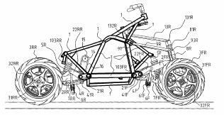
WO2008012251 |
Motorcycle |
2008-02-06 |
Luciano Marabese Riccardo Marabese Norisha Mochizuhi Timmy Meisner |
EP1155950 (see 2F3T) WO2005037637 EP0626307 (see 1F3T) |
DE3611417 (see
1F1T; 1F3T) FR2616405 (see 1F3T) WO2004056645 (see 2F3T) |
EP1918187 |
2F4T |
|
Figure |
Abstract |
||||||
|
|
A four wheeled motorcycle vehicle, comprising: a
frame (1) having vertical, longitudinal and lateral orientations in the
upright position of the vehicle; two pairs of two spaced apart swing arms
(2FR,2RR) pivotally mounted thereon at both ends on substantially laterally
extending swing pivot axes (21F,21R), which swing arms (2FR,2RR) extend in a
substantially longitudinal direction in the upright position of the vehicle,
wherein each swing arm (2FR,2RR) bears a front (3FR) or rear (3RR) wheel at
its other end on a wheel axis (31FR,31RR); balancer beams (6F,6R) rotatably
mounted on rotation axes (61F) on the frame (1) near their centre; and a pair
of at least two linking rods (7FR,7RR), each linking rod (7FR,7RR) being
pivotally connected to one end of a balancer beam (6F,6R) at one end and
being pivotally connected to one of said swing arms (2FR,2RR) at its other
end.; In the upright position of said vehicle one end of each of said linking
rods (7FR,7RR) is positioned below the swing plane extending trough both
swing pivot axes (21F,21R) and both wheel axes (31FR,31RR) of each pair of
swing arms (2FR,2RR), and the other end of each of said linking rods
(7FR,7RR) is positioned above said swing plane. |
||||||
|
Patent number |
Title of
the patent |
Publication
date |
Inventor
(s) |
Documents cited by the inventor (s) |
Cited documents in search report |
Other patents where this patent is cited in
search report |
Field of
application |
|
System to control the trim of motorcycles with three
or four wheels |
2008-01-31 |
Luciano Marabese |
WO0244008 WO9727071 |
EP1362779 EP1520775 DE9414724 WO0244008 WO9727071 |
None |
1F3T; 2F4T |
|
|
Figure |
Abstract |
||||||
|
|
It is described a system to control the trim of
motorcycles with three or four wheels, including for each couple of wheels a
system of levers (1) linking the hubs of the wheels v(7, 8) belonging to the
couple, a shock absorber and one or more dampers (5) directly installed
between said wheels v(7,8), or between said system of levers v(1) and a fixed
point v(51) on the vehicle frame or chassis. |
||||||
|
Patent number |
Title of
the patent |
Publication
date |
Inventor
(s) |
Documents cited by the inventor (s) |
Cited documents in search report |
Other patents where this patent is cited in
search report |
Field of
application |
|
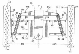
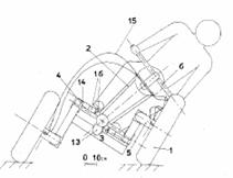
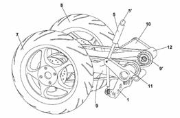
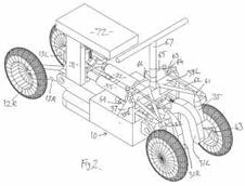
A suspension tilting module for a wheeled vehicle
and a wheeled vehicle equipped with said suspension tilting module |
2007-12-26 |
Stefano Carabelli Andrea Tonoli Andrea Festini Fabio Cavalli |
None |
GB2310838 US2260102 DE19717418 DE19619644 WO8100088 EP0528783 |
None |
2F3T; 2F4T |
|
|
Figure |
Abstract |
||||||
|
|
A tilting suspension system is provided for two
wheels (2, 3) of a vehicle (200) disposed on a common axle with said module
comprising a rigid frame (17) adapted to be firmly fixed to the chassis of
the vehicle so as to be tilted together with the whole vehicle and a tilting
arm (14) pivotally linked to said rigid frame. The tilting of the rigid frame
is obtained as a result of the counter torque arising when activating
hydraulic actuating means (101, 102) pivotally interposed between said
tilting arm (14) and said rigid frame (17), with said tilting arm being
pivotally connected to shock absorbers (18). The tilting module further
comprises suspension arms (10, 11, 12, 13) pivotally connected to the rigid
frame, with said suspension arms supporting, in cooperation with supporting
uprights, the two wheels thus allowing both tilting and steering of said two
wheels.; The hydraulic actuating means (101, 102) are actuated by an
hydraulic pump (112) driven by an electric motor (108). |
||||||
|
Patent number |
Title of
the patent |
Publication
date |
Inventor
(s) |
Documents cited by the inventor (s) |
Cited documents in search report |
Other patents where this patent is cited in
search report |
Field of
application |
|
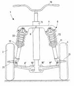
US2010044977 EP2019772 |
Vehicle with lockable tilt system |
2007-11-08 |
Peter S Hughes Andrew H Twombly Craig Bliss |
WO9843872 (see 1F3T) EP1180476 (see 2F3T) US6326765 (Two
wheeler) US20050092538 US6724165 |
US5762351 (Human powered) EP0876263 DE3611417 (see 1F1T; 1F3T) US2887322 WO0136253 (see 1F3T) US4740004 EP1180476 (see 2F3T) |
WO2009153578 EP2127920 |
1F3T; 2F3T; 2F4T |
|
Figure |
Abstract |
||||||
|
|
A vehicle that includes a vehicle body and a vehicle
support assembly. The vehicle body has a longitudinal axis and is configured
for supporting a rider thereon. The support assembly includes first (421A)
and second (421B) tilting wheels disposed respectively at different lateral
positions with respect to the longitudinal axis, a tilt-mechanism (452)
supportively associating the vehicle body from the tilting wheels to enable
the vehicle body to tilt throug\h a first tilt range with respect to a
surface on which the tilting wheels are disposed, and a tilt-limiter (456)
operably associated with the tilt-mechanism (452) to restrict the tilting of
the vehicle body to less than the first tilt range, and releasable to allow
the tilting through the first tilt range . |
||||||
|
Patent number |
Title of
the patent |
Publication
date |
Inventor
(s) |
Documents cited by the inventor (s) |
Cited documents in search report |
Other patents where this patent is cited in
search report |
Field of
application |
|
Vehicle |
2007-04-19 |
Akihiro Yanaka Yoshikazu Motozono Yasukazu Honnda |
? |
JP2005112300 JP2005082044 JP3253476 JP8034353 JP4125712 JP58018870 JP2006219033 JP2004123080 JP3026673 WO2005077683 JP2005112300 JP2005082044 |
None |
1F3T ; 2F4T |
|
|
Figure |
Abstract |
||||||
|
|
A vehicle with increased turning ability. When the
vehicle turns, left and right wheels are moved relative to a vehicle body in
the top-bottom direction, and this causes the body and the left and right
wheels to tilt to the inside of the turn. This causes force acting on a
vehicle occupant to be in the top-bottom direction of the occupant, reducing
unpleasant feeling of the occupant. Also, since the center of gravity of the
vehicle moves to the inside of the turn, turn stability is increased. |
||||||
|
Patent number |
Title of the patent |
Publication date |
Inventor (s) |
Documents cited by the
inventor (s) |
Cited documents in search
report |
Other patents where this
patent is cited in search report |
Field of application |
|
Self-balancing
vehicle |
2006-12-07 |
Christopher Van Den Brink |
WO9534459 (see 1F3T) WO9914099 (See 1F1T) EP0941198 NL1000161 NL20041026658 WO9924308 (See 1F1T) WO0187689 (See 1F1T) |
US6435522 (see 1F1T WO9924308) US4484648 US4660853 WO9534459 (see 1F3T) FR2646379 (see 1F3T) |
1F3T ; 2F3T ;
2F4T |
||
|
Figure |
Abstract |
||||||
|
|
A vehicle comprises: - at least
three wheels, of which at least two wheels are situated on either side of the
centre of gravity of the vehicle's longitudinal axis and wherein at least one
of the wheels has a steering effect on the direction of the vehicle, - a
frame consisting of a tilting frame section, wherein said frame section can
rotate in the longitudinal axis relative to the road surface, - a steering
means which is mounted so that it can rotate relative to the tilting frame
section, - one or more tilting elements which are connected to the tilting
frame section and the wheels for exerting a tilting moment and/or tilting
movement between the tilting frame section and the road surface, - a speed
sensor with which the speed of the vehicle relative to the road surface can
be determined,; - a steering sensor with which the force/the torque or the
size of the steering wheel movement for achieving a change in the direction
of the steerable wheel or the steerable wheels can be determined. Furthermore
a lateral acceleration sensor with which the lateral acceleration of the
tilting frame section of the vehicle can be determined. A method for the tilt
control of this vehicle is characterised in that the signal from the steering
sensor, the signal from the lateral acceleration sensor and the signal from
the speed sensor are used as control signal to control the tilting elements. |
||||||
|
Patent number |
Title of
the patent |
Publication
date |
Inventor
(s) |
Documents cited by the inventor (s) |
Cited documents in search report |
Other patents where this patent is cited in
search report |
Field of
application |
|
Land or waterborne vehicle and chassis frame of such
a vehicle |
2006-10-19 |
Philippe Missakian |
None |
EP1142779 EP1516801 GB2279047 (see 1F3T; 2F3T) GB2300163 DE29705386U DE4135585 |
None |
2F4T |
|
|
Figure |
Abstract |
||||||
|
|
The invention concerns a land or waterborne vehicle
(1) comprising a chassis frame having a longitudinal axis (X), characterized
in that the chassis frame (4) includes at least one pivot type articulation
(20), with pivot pin parallel to said longitudinal axis and an assembly (5,
6; 13-16) forming an articulated quadrilateral, in particular a parallelogram
or trapezium. |
||||||
|
Patent number |
Title of
the patent |
Publication
date |
Inventor
(s) |
Documents cited by the inventor (s) |
Cited documents in search report |
Other patents where this patent is cited in
search report |
Field of
application |
|
System to build a steerable and inclinable vehicle
with 3 or 4 wheels |
2006-07-13 |
Gianfranco Cecinini |
None |
EP1155950 (see 2F3T) EP1180476 (see 2F3T) US4375293 US4351410 US2002190494 EP1090832 WO9709223 US4360224 DE29705386U JP1168585 JP1229787 |
WO2009069170 |
2F3T; 2F4T |
|
|
Figure |
Abstract |
||||||
|
|
The necessity to get higher degrees of safety
through better stabilities of the "Scooter-Cyclemotor-
Bicycle-Motorcycle" has made theese 2 kinds of assemblies (front and
rear) . The Front assembly always has forwarding the" 2 steering,
inclining, shock-absorbing, braking, parallel front wheels" and with the
already existent 1 rear-wheel in the rear side, or with the Rear-assembly,
that has the"2 inclining, shock-absorbing, braking, parallel
rear-wheels" (Page :1 ,2,3,4,5,6,7. / 7) . Those 2 kind of assemblies
are singularly, or both, suitable to build a vehicle with' 3, or 4 wheels'
(with 2 rear-wheels) , always determining 3 or 4 points of contact on the
ground (not only 2 ) . The vehicle with '3, or 4 wheels' is safer, it's more
vertical steady and answers the highest degrees safeties either, with a
second passenger on board, or with major loads upon (like heavier
accumulators use for electtric or hybrid power and/or if it uses major
load-structures like new body carriage) . The vehicle is always safe
especially when adverse metheo-conditions happen (stormy weather, snowing,
hailing etc.) , or in specific unbalanced conditions (like in up or down
dangerous pending roads "in uphill or downhill") . Then the
Front-assembly with, or w/o the Rear-assembly offers the following advantages
in : .A) STAND UP STABILITY in ' parking mode' .B) STAND UP STABILITY in '
marching and in turning mode' (without or with braking) .C) AGILITY inside SECURITY
either in th urban traffic or in highways. .D) GOOD ROADABILITY. |
||||||
|
Patent number |
Title of
the patent |
Publication
date |
Inventor
(s) |
Documents cited by the inventor (s) |
Cited documents in search report |
Other patents where this patent is cited in
search report |
Field of
application |
|
|
Motor vehicle for e.g. urban zone, has balancing
unit balancing in bends or on ground inclined with respect to horizontal, by
simultaneous inclination of chassis and front wheels, and blockage unit
blocking inclination of vehicle |
2006-01-13 |
Daniel Moulene Thierry Moulene |
None |
US6149226 FR2831866 BE1010650 US4921263 WO9849023 DE29610254U US4609221 WO9954188 DE19608578 |
GB2438268 FR2899556 EP1813450 |
2F4T |
|
Figure |
Abstract |
||||||
|
|
The vehicle has a balancing unit for balancing in
bends or on ground inclined with respect to horizontal, by simultaneous
inclination of a chassis (3) which is integrated with a driver's compartment
of a vehicle and two front wheels (10) of the vehicle with respect to the
ground. A blockage unit blocks the inclination of the chassis and the wheels
of the vehicle, when the vehicle is stopped. |
||||||
|
Patent number |
Title of
the patent |
Publication
date |
Inventor
(s) |
Documents cited by the inventor (s) |
Cited documents in search report |
Other patents where this patent is cited in
search report |
Field of
application |
|
Motor Vehicle with limited angle of inclination |
2006-01-12 |
Daniel Moulene Thierry Moulene |
US6149226 FR2831866 |
WO9709223 GB2279047 (see 1F3T; 2F3T) FR2836447 |
None |
2F4T |
|
|
Figure |
Abstract |
||||||
|
|
The invention relates to a motor vehicle ( 1 ) of
the type with four wheels ( 10 ), which consists of: a driver's cab which is
only large enough to accommodate one person widthways and which is solidly
connected to a chassis comprising a driver protection structure ( 4 ); and
means for balancing the vehicle when negotiating bends and/or on surfaces
that are inclined in relation to the horizontal, by inclining the chassis and
the two front wheels simultaneously. The vehicle also comprises
inclination-locking means which are actuated automatically when the vehicle
is stopped or travelling at a reduced speed. The inventive vehicle further comprises
means for limiting the angle of inclination to a maximum value such that,
when stopped, the vehicle does not tilt. |
||||||
|
Patent number |
Title of
the patent |
Publication
date |
Inventor
(s) |
Documents cited by the inventor (s) |
Cited documents in search report |
Other patents where this patent is cited in
search report |
Field of
application |
|
US2004051269 US7494141 |
Four wheel drive stationary body vehicle with
controlled wheel and passenger compartment lean, with independent steering |
2005-09-22 |
Todd Bouton |
US4650213 US4632413 US4624469 US4600217 US4159128 US2961254 US2819093 US980508 |
None |
US7648148 WO2010001397 US2006123763 |
2F4T |
|
Figure |
Abstract |
||||||
|
|
In this vehicular chassis system, the vehicle's
passenger compartment and wheels incline toward the turning center side in
such a manner, that the wheels can be tilted independently from steering.
This vehicle has a steering apparatus controlling the steering, and a
separate apparatus controlling the lateral leaning. The lean is controlled
mechanically using a pendulum, and forced lateral leaned using a control
unit, or manually with the transfer of body weight using several pinions with
a set ratio to control the passenger compartment lateral lean in conjunction
with the wheel lateral lean.; An electric DC servo gear motor can be used to
control the lateral lean, that intern moves a pinion, which moves a rack and
lateral movable cross member, while controlling the lateral leaning wheels
and pulling the tilt support bar pivotally attached to a passenger
compartment in the same leaning direction. |
||||||
|
Patent number |
Title of
the patent |
Publication
date |
Inventor
(s) |
Documents cited by the inventor (s) |
Cited documents in search report |
Other patents where this patent is cited in
search report |
Field of
application |
|
EP1694555 |
Four-wheeled vehicle |
2005-06-30 |
Maurizio Marcacci |
None |
GB2279047 WO0192084 DE20101192 US4180280 US3783961 DE3044899 EP0626307 US4657271 EP1155950 US4066142 |
EP1864843 EP1894753 |
2F4T |
|
Figure |
Abstract |
||||||
|
|
Four-wheeled vehicle (1) of the type equipped with
two steered front wheels (2, 3), a frame (13), handlebars (16), two rear
wheels (4, 5) and a front suspension group (6) that acts upon the two front
wheels (2, 3) . The front suspension group (6) allows the rolling of the
vehicle (1). |
||||||
|
Patent number |
Title of
the patent |
Publication
date |
Inventor
(s) |
Documents cited by the inventor (s) |
Cited documents in search report |
Other patents where this patent is cited in
search report |
Field of
application |
|
Laterally-leaning four wheeled vehicle |
2005-04-28 |
Rodney Rawlinson |
None |
WO03057549 EP1155950 (see 2F3T) US2002190494 EP0626307 (see 1F3T) FR2522590 WO9727071 (see 1F3T) GB2279047 (see 1F3T; 2F3T) |
None |
2F4T |
|
|
Figure |
Abstract |
||||||
|
|
This invention relates to wheeled vehicles and
particularly to motorised road vehicles. The wheeled vehicle (10) includes
two frames (12) for carrying road wheels (18, 20), the frames (12) being
laterally spaced apart. A pair of road wheels (18, 20) are mounted on each
frame (12) for supporting that frame (12) on the ground, the wheels (18, 20)
of each pair being mounted for rotation about operatively more or less
horizontal rotational axes which are spaced apart along the associated frame
(12). A motor (36) is connected by a drive train (48, 28, 30, 32) to a rear wheel
(20) on each of the wheeled frames (12). The wheeled frames (12) are
connected together for synchronous tilting relative to the vertical, so that
the camber angles of all the wheels (18, 20) change in response to lateral
tilting of the frames (12). |
||||||
|
Patent number |
Title of
the patent |
Publication
date |
Inventor
(s) |
Documents cited by the inventor (s) |
Cited documents in search report |
Other patents where this patent is cited in
search report |
Field of
application |
|
Motorcycle-type
vehicles |
2003-11-19 |
Nicholas Richard
Shotter |
None |
WO0244008 US4756379 US4887829 EP1142779 EP0606191 FR2550507 FR2522590 WO9941136 WO03018390 |
WO2008012251 WO2008011917 |
2F4T |
|
|
Figure |
Abstract |
||||||
|
|
A motorcycle-type vehicle has two front wheels and
two rear wheels. The vehicle chassis (10) is supported on the front wheels by
J-shaped swing arms (31) each forming one side of a quadrilateral linkage
which includes struts (35) and upper wishbone members (38). The front swing
arms are linked to opposite ends of a balance beam (52) pivoted on a carriage
(53) movable on linear guides (54) against the action of a spring unit (55).
Individual dampers (D) act on the swing arms and can be locked electrically or
hydraulically in an emergency. A similar arrangement is used for
rear swing arms (13). |
||||||
|
Patent number |
Title of
the patent |
Publication
date |
Inventor
(s) |
Documents cited by the inventor (s) |
Cited documents in search report |
Other patents where this patent is cited in
search report |
Field of
application |
|
Vehicle with three or more wheels has body that can
be tilted on bends |
2003-08-29 |
Jean Guizard |
FR2796594 FR2560122 |
US4359231 US4469344 |
EP19223303 W02006003489 |
2F4T |
|
|
Figure |
Abstract |
||||||
|
|
The vehicle, which has at least one rear wheel (5a,
5b) and two front wheels (6a, 6b), has a system that allows its body and
chassis to tilt on bends so that the wheels on one side are above and the
wheels on the other side are below a reference plane (Pr) perpendicular to
the saggital plane of the chassis. The tilting movement is produced when the
steering handlebar (15) is turned to left or right, by means of a steering
bar (12) connected to the wheel hubs by horizontal arms (9a, 9b) and vertical
rods (16a, 16b) in guides (17a, 17b), and a connecting piece (14) between the
bar (12) and the steering column (13). |
||||||
|
Patent number |
Title of
the patent |
Publication
date |
Inventor
(s) |
Documents cited by the inventor (s) |
Cited documents in search report |
Other patents where this patent is cited in
search report |
Field of
application |
|
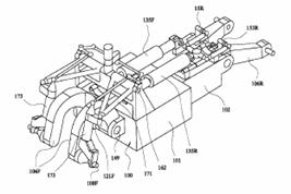
Motorcycle-type vehicle |
2002-06-06 |
Richard Nicholas
Shotter |
None |
US4756379 US4828069 US4890857 DE19823002 US4020914 |
EP1918187 WO2008011917 EP1571016 (see 2F3T) EP1378428 WO2004056645 (see 2F3T) |
2F3T ; 2F4T |
|
|
Figure |
Abstract |
||||||
|
|
The or each front wheel (4) of the vehicle is
mounted on a stub axle (108F) at the lower end of a strut (173) articulated
in the central plane of the wheel to one end of an inverted U or J-shaped
suspension arm (106F) pivotally mounted on its other end on the vehicle
chassis and forming a parallelogram linkage with a wishbone member (171),
pivoted at (162) thereby providing constant trail for the wheel. To provide
increased stability, the vehicle can have two front wheels (4) and two rear
wheels (5) mounted on respective swing arms (106F) and (106R) respectively
and the swing arm movements can be restricted by stabilising brakes (121F)
and (1 |
||||||
|
Patent number |
Title of
the patent |
Publication
date |
Inventor
(s) |
Documents cited by the inventor (s) |
Cited documents in search report |
Other patents where this patent is cited in
search report |
Field of
application |
|
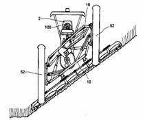
Vehicle suspension
systems |
1998-06-30 |
Chi-Kwan Tong |
None |
US4277076 US4830394 US5116069 US5230529 US5529324 |
GB2439297 EP1459917 (irrelevant) US2002109310 EP1110768 EP0983883 |
2F4T |
|
|
Figure |
Abstract |
||||||
|
|
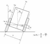
A vehicle suspension system is provided for tilting a
chassis 24 with respect to the axes of vehicle wheels 31 and 32 during
cornering to improve the comfort of travel for occupants of the vehicle. A
lateral or centrifugal force sensor mounted to the chassis 24 provides a
control for a hydraulic pump to cause a piston 15 in a cylinder 14 to move to
the left or right. The Figure shows the piston 15 to the left of a mean
central position and its movement has caused the chassis to tip to the right.
The vehicle in the Figure is shown moving away and to the right. For the
corner, the tilt is stable as the sensor will remain balanced, that is not
then generating further or extra tilting, until the degree of cornering
changes or the vehicle straightens out. In the latter case, the sensor will
respond to cause the piston 15 to move to its central position and the
chassis to level off. |
||||||
|
Patent number |
Title of
the patent |
Publication
date |
Inventor
(s) |
Documents cited by the inventor (s) |
Cited documents in search report |
Other patents where this patent is cited in
search report |
Field of
application |
|
Four-wheeled motor vehicle with inwardly-inclining
body and wheels on bends |
1997-03-13 |
Mario Infante |
None |
GB2279047 (see 1F3T;
2F3T) GB775405 AT394694 EP0626307 (see 1F3T) |
WO2006072971 WO2006003489 WO2005051689 US2004079561 WO9928179 |
2F4T |
|
|
Figure |
Abstract |
||||||
|
|
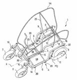
The invention of this particular vehicle, due to its
special characteristics, is an important innovation in solving the problems
of traffic jams and parking spaces. It has the manoeuvrability of a motorcycle,
and all the comforts of a car. Its characteristics are: 1) reduced size, with
seats (preferably three) positioned in a longitudinal direction; 2)
inclination of the vehicle through the internal side of the curve (such as
with a motorcycle). The second point is possible because of the anti-rolling
system. It works by a system of ascending and descending wheels; ascending if
they are internal to the curve, descending for the outside, controlled by the
driver with a common bar normally used on motorcycles. The same bar can also
be inclined to lean the vehicle either to the left or to the right. This
system can also be used in traditional cars, off-road vehicle and
three-wheeled vehicles, as it would improve their safety in curves at higher
speeds. |
||||||
|
Patent number |
Title of
the patent |
Publication
date |
Inventor
(s) |
Documents cited by the inventor (s) |
Cited documents in search report |
Other patents where this patent is cited in
search report |
Field of
application |
|
Four-wheeled motor vehicle with the action of a
motor- |
1994-04-13 |
Rino Calzolari |
None |
EP0020835 EP0502830 US4064957 GB2120184 (see 1F1T; US4423795) US4717164 (human powered) |
WO2005075278 WO2005030559 US5927424 WO9534459 (see 1F3T) |
2F4T |
|
|
Figure |
Abstract |
||||||
|
|
The rear wheels are mounted on a tail unit (20)
which can be orientated about an axis lying substantially in the vertical
plane of longitudinal symmetry of the vehicle and which is horizontal or
virtually horizontal, and means are provided which can orientate the chassis
(1) of the vehicle with respect to the said tail unit in accordance with the
angular movement of the steering handle-bars (74), to provide the inclined
geometry of the vehicle around bends. |
||||||
|
Patent number |
Title of
the patent |
Publication
date |
Inventor
(s) |
Documents cited by the inventor (s) |
Cited documents in search report |
Other patents where this patent is cited in
search report |
Field of
application |
|
Vehicle suspension |
1987-03-03 |
Daniel Paquette Real Paquette Roger Paquette |
US2417019 US2473519 |
US1978498 US2417019 US2473519 US3175637 US3266815 |
US2006290083 US2006123763 US2005257965 US2004160031 US2004160030 US6625967 US6357766 WO0009913 US6305487 US6279931 US5921338 WO9115375 US4923257 US4881748 |
1F3T 2F4T |
|
|
Figure |
Abstract |
||||||
|
|
The suspension includes a pair of arms independently
pivoted to opposite sides of the vehicle chassis at one end for up-and-down
movement, each arm rotatably carrying a ground-engaging wheel of the vehicle
at its free end. Each arm extends in the same direction from its pivoted end,
longitudinally of the chassis. A compression spring contacts and upwardly
extends from each arm at a distance from its pivoted end, and a load transfer
lever is fulcrumed at its center to the chassis; extends transversely of the
latter; and its outer ends overly and contact the top of the respective
compression springs. The suspension system is applicable to three- and
four-wheel motor vehicles. Preferably, the arms are hollow and serve to house
part of a transformation mechanism to the wheels, the latter being the
driving wheels.; In a four-wheel vehicle in accordance with the invention,
there is further provided an additional load transfer lever disposed on each
side of the vehicle chassis and extending longitudinally of the same, with
their ends underlying and having a slidable connection with the first-named
transfer levers adjacent the springs. |
||||||
|
Patent number |
Title of
the patent |
Publication
date |
Inventor
(s) |
Documents cited by the inventor (s) |
Cited documents in search report |
Other patents where this patent is cited in
search report |
Field of
application |
|
Body banking suspension apparatus for a vehicle |
1986-12-30 |
Masao Ogawa Kenji Honma Harayasu Fujita |
JP5425033 |
US2852268 US4360224 US4546997 |
US7185902 US2005248116 DE10358522 WO03057517 WO03059663 US6109621 US5765846 WO9615006 US4903857 (Human powered) US4840393 US4717164 (human powered) |
2F3T 2F4T |
|
|
Figure |
Abstract |
||||||
|
|
A suspension apparatus for a vehicle adapted to
decline the body and/or the wheels toward the turning center side according
to the steering operation when the vehicle makes a turn. In this suspension
apparatus, the end portion of a suspension spring at the vehicle body side or
the end portion of an upper arm at the vehicle body side are secured to a
movable member associated with a steering operation member for movement. In
the vehicle equipped with this suspension apparatus, driver can enjoy the
similar steering sense or feeling as a motorcycle. |
||||||
|
Patent number |
Title of
the patent |
Publication
date |
Inventor
(s) |
Documents cited by the inventor (s) |
Cited documents in search report |
Other patents where this patent is cited in
search report |
Field of
application |
|
Vehicle tilting
device |
1986-10-13 |
Yoshinori Kawashima Masao Ogawa Haruyasu Fujita |
¿ |
None |
US5040812 |
2F3T 2F4T |
|
|
Figure |
Abstract |
||||||
|
|
PURPOSE:To enhance the turnability of a vehicle
having at least one set of left and right wheels in pair, by arranging such
that the vehicle automatically tilts toward the center of turn of the vehicle
in accordance with the steering operation of the vehicle so that control
feeling similar to a motor-cycle may be obtained. CONSTITUTION:When a
steering wheel 20 is rotated in the direction (a) to turn a vehicle to, for
example, the right during running of the vehicle, a slide shaft 13 is moved
leftward through a pinion 18 to deflect a front wheel 1 rightward.; Further,
simultaneously hydraulic pressure is fed into a cylinder 23 in a suspension
device 14 on the left side (right side in the figure) through a fluid
change-over device (rotary valve) which is not shown and which is operated in
association with the rotation of the steering wheel while hydraulic oil is
discharged from a cylinder 23 in a right side suspension device 14. With this
arrangement, the left side cylinder 23 is moved upward while the right side
cylinder 23 is moved downward, thereby a vehicle body 2 is inclined rightward
or toward the center of turn through a lower arm 4 and an upper arm 6. |
||||||
|
Patent number |
Title of
the patent |
Publication
date |
Inventor
(s) |
Documents cited by the inventor (s) |
Cited documents in search report |
Other patents where this patent is cited in
search report |
Field of
application |
|
Suspension apparatus
for vehicle |
1985-09-25 |
Takahisa Suzuki Masao Ogawa Kenji Honma Harayasu Fujita |
JP5425033 |
GB2039834 GB869984 GB836298 GB796683 GB720551 |
EP1799472 WO0192084 US6109621 US5927424 WO9534459 (see 1F3T) |
2F3T 2F4T |
|
|
Figure |
Abstract |
||||||
|
|
Telescopic members (241, 242) which are expanded and
contracted by means of a fluid pressure controlled by a steering mechanism
(20) are integrally connected to suspension springs (141, 142). When a
vehicle makes a turn, the body is caused to decline toward the turning center
side due to the telescopic movement of the telescopic members according to
the steering operation. The fluid pressure may be fed from a hydraulic
cylinder (26) including a piston (27) associated for movement with the
steering mechanism. Alternatively, fluid pressurized by a pump may be fed
through a controlling valve which is actuated in response to the steering
mechanism. At a time when the vehicle makes a turn, a satisfactory steering
sense similar to a motorcycle can be obtained. |
||||||
|
Patent number |
Title of
the patent |
Publication
date |
Inventor
(s) |
Documents cited by the inventor (s) |
Cited documents in search report |
Other patents where this patent is cited in
search report |
Field of
application |
|
Vehicle stabilization
system |
1966-10-11 |
Li Yao-Tzu |
None |
US2178351 US2555034 US2569402 US2579570 US2584125 |
US2007068725 US5845896 US5440817 WO9406642 US5065522 US4877201 DE3800246 US4691798 US4531300 US4266790 US4276975 US4200168 US4087108 US4054300 US3974699 US3465840 US3490059 US3373832 US3410357 US3375722 |
1F3T 2F4T |
|
|
Figure |
Abstract |
||||||
|
|
Not available |
||||||
|
Patent number |
Title of
the patent |
Publication
date |
Inventor
(s) |
Documents cited by the inventor (s) |
Cited documents in search report |
Other patents where this patent is cited in
search report |
Field of
application |
|
Equalizer type vehicle suspension and locking means
therefor |
1959-05-19 |
Louis De Monge |
None |
US931653 US1427240 DE211367 GB704270 |
WO03045719 WO9727071 (see 1F3T) US4903790 US4600216 FR2547249 US4283074 US4050712 US4087108 US4054300 US4065144 US4003443 US3909022 US3601213 US3430724 US3108552 |
1F3T 2F4T |
|
|
Figure |
Abstract |
||||||
|
|
Not available |
||||||
|
Patent number |
Title of
the patent |
Publication
date |
Inventor
(s) |
Documents cited by the inventor (s) |
Cited documents in search report |
Other patents where this patent is cited in
search report |
Field of
application |
|
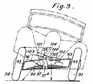
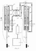
US2260102 |
Automobile vehicle |
1939-02-23 |
Paul Léon Freret |
None |
None |
WO9727071 FR2557039 FR2522590 |
2F4T |
|
Figure |
Abstract |
||||||
|
|
None |
||||||