|
1900-1909 |
1910-1919 |
1920-1924 |
1925-1929 |
1930-1934 |
1935-1939 |
1945-1949 |
1950-1954 |
1955-1959 |
|
|
|
|
|
|
|
|
|
|
|
|
|
1960 |
1961 |
1962 |
1963 |
1964 |
1965 |
1967 |
1969 |
||
|
|
|
|
|
|
|
|
|
|
|
|
1970 |
1971 |
1972 |
1973 |
1974 |
1975 |
1977 |
1979 |
||
|
|
|
|
|
|
|
|
|
|
|
|
1980 |
1981 |
1982 |
1983 |
1984 |
1985 |
1987 |
1989 |
||
|
|
|
|
|
|
|
|
|||
|
1990 |
1991 |
1992 |
1993 |
1994 |
1995 |
1997 |
1999 |
||
|
|
|
|
|
|
|
||||
|
2000 |
2001 |
2002 |
2003 |
2004 |
2005 |
2007 |
2009 |
||
|
|
|
|
|
|
|
|
|
|
Patent number |
Title of
the patent |
Publication
date |
Inventor
(s) |
Documents cited by the inventor (s) |
Cited documents in search report |
Other patents where this patent is cited in
search report |
Field of
application |
|
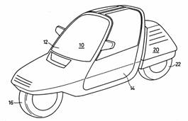
Apparatus for shifting the center of gravity of a
vehicle having three wheels or more and a lozenge-shaped automobile having
the same |
2007-10-25 |
Je-Woo Yu |
None |
US4717164 EP1142779 JP11011372 |
None |
1F1T; Miscellaneous |
|
|
Figure |
Abstract |
||||||
|
|
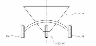
An apparatus for shifting the center of gravity for use
in a vehicle having three wheels or more, and a lozenge- shaped automobile
having the same are provided. The apparatus comprises a stationary chassis, a
movable chassis, and a gear device for moving the movable chassis relative to
the stationary chassis. The stationary chassis is disposed perpendicular to
the forward direction of the automobile, and has a stationary rail. The
stationary rail is formed in a circular shape having, as the origin, a point
on the line projected on the ground from the longitudinal center line of the
car body parallel to the forward direction of the automobile. The movable
chassis is disposed parallelto the forward direction of the automobile, and
has a moving rail engaged with the stationary rail so as to move therealong.
The moving rail moves to the left/right relative to the forward direction
along the stationary rail. A moving gear is installed on the movable chassis
parallel to the moving rail. A rotating gear is installed on the stationary
chassis so as to be engaged with the moving gear. A ball screw device is
installed so as to be engaged with the rotating gear. The lozenge- shaped
automobile having the above construction includes a steering unit for
simultaneously steering three front wheels in the forward direction of the
automobile. |
||||||
|
Patent number |
Title of
the patent |
Publication
date |
Inventor
(s) |
Documents cited by the inventor (s) |
Cited documents in search report |
Other patents where this patent is cited in
search report |
Field of
application |
|
Laterally leanable
vehicle |
2001-10-10 |
Lars Jansson |
None |
FR2338836 DE136862 DE804527 GB191415303 JP6064083 |
WO2007119918 WO2006108997 EP1362779 |
Miscellaneous |
|
|
Figure |
Abstract |
||||||
|
|
Laterally leanable vehicle having a frame means
connecting a front main support member (1) and a rear main support member
(2), and lateral supporting members (4,5) disposed on both sides of the
vehicle, said lateral supporting members (4,5) are pivotably supported around
a pivot axis (17,62) on said frame means, wherein at least in an upright
non-leaned position of said vehicle said pivot axis (17,62) extends in a
longitudinal vertical plane (29,63) of the vehicle and close to a center of
gravity (28,TP) of the vehicle. |
||||||
|
Patent number |
Title of
the patent |
Publication
date |
Inventor
(s) |
Documents cited by the inventor (s) |
Cited documents in search report |
Other patents where this patent is cited in
search report |
Field of
application |
|
Stabilising frame for motor bicycles |
1998-05-22 |
Michel Pudlo |
FR2700501 EP606191 WO9301965 |
FR2550507 DE3611417 EP0606191 GB2133358 US4186934 JP4317882 |
None |
Miscellaneous |
|
|
Figure |
Abstract |
||||||
|
|
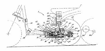
The stabilising frame has a cradle (13) to be
attached to the base of the scooter frame to support a triangular frame (12)
extended by a bearing (9). There are two wheels (2a,b) fixed to a drive shaft
(52) and a swinging cross member (3) which is controlled by a cable (26)
extending from the front fork pivot of the scooter. There is an arm (6a) with
two orthogonal arcs articulated at the middle of the axle (3) on the hub (4)
with the axis (5a) oriented perpendicularly to the centre of the line of the
axles of the wheels and to the head of the T-shaped spindle. |
||||||
|
Patent number |
Title of the patent |
Publication date |
Inventor (s) |
Documents
cited by the inventor (s) |
Cited
documents in search report |
Other
patents where this patent is cited in search report |
Field of application |
|
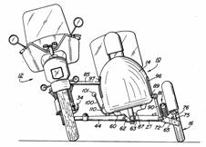
Motorcycle side car frame |
1993-08-24 |
Ghislain Michaud |
US385770 |
US2702196 US2793051 US3960391 US4022483 US4078815 US4254965 US4385770 US4415056 US4477097 US4548419 CA1050071 EP0352132 FR789634 |
US2004026889 DE10152605 US2002148664 |
Miscellaneous |
|
|
Figure |
Abstract |
||||||
|
|
A side car for a motorcycle, wherein the side car box overlies the
side car wheel directly thereabove. The lateral coupler between the side car
and the motorcycle biases the side car wheel to incline interiorly of a
curve, together with the motorcycle wheels, upon the moving vehicle taking a
curve on a road. The side-car frame and box axially roll with the wheel,
whereby the side-car center of gravity remains continuously within the plane
of its wheel. As the motorcycle wheels progressively axially roll, their
angular value relative to the vertical plane will increase relative to a
second angular value corresponding to the roll of the side-car wheel relative
to the vertical plane. |
||||||
|
Patent number |
Title of
the patent |
Publication
date |
Inventor
(s) |
Documents cited by the inventor (s) |
Cited documents in search report |
Other patents where this patent is cited in
search report |
Field of
application |
|
Traveling vehicle |
1993-07-20 |
Toichiro Hikichi Seiichi Urashi |
None |
None |
EP0820924 |
Miscellaneous |
|
|
Figure |
Abstract |
||||||
|
|
PURPOSE:To permit the self erection on stop and
provide the steering feeling which is nearly same to that of a motorcycle.
CONSTITUTION:A rear fork 9 for supporting left and right rear wheels Wr for a
car body frame 1 which supports front wheels Wf is pivotally supported in
vertically swingable manner through a pivot 10, and the car body is erected
by the front and rear wheels Wf and Wr on stopping the left and right rear
wheels Wr are applied with the plus camber, and the distance between the
grounded parts of both the rear wheels Wr is set small, and then the bank of
the car body is facilitated, and the turning performance is improved.; Both
the rear wheels Wr can be steered in the reverse phase to the steering
direction of the front wheels Wf by the lateral force applied from a road
surface by the action of the plus trail T, and can be steered positively to
the reverse phase or same phase for the front wheels Wf by an actuator using
a motor as drive source. |
||||||
|
Patent number |
Title of
the patent |
Publication
date |
Inventor
(s) |
Documents cited by the inventor (s) |
Cited documents in search report |
Other patents where this patent is cited in
search report |
Field of
application |
|
Automatic rolling mechanism for vehicle |
1992-05-18 |
Takeji Nakanishi |
None |
None |
None |
Miscellaneous |
|
|
Figure |
Abstract |
||||||
|
|
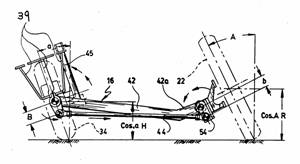
PURPOSE:To take a bank posture in a curve running
and to improve the cornering performance by providing a pair of wheel members
combined rotatable at both ends of a lateral member and holding the left and the
right wheels at the free ends, a connecting member to connect the both wheel
members and a car body, and the like. CONSTITUTION:In a rolling mechanism 30
suitable to a motorbike of the type furnishing one front wheel and two rear
wheels and having the car body separated into the front part and the rear
part, the central part of a lateral member 32 is connected to a part of the
front part 10 of the car body by a rolling shaft 28 to roll freely, and the
upper ends of a pair of V-shaped left and right wheel members 40 are pivoted
42 to both ends of the lateral member 32.; And at the middle parts of both
wheel members 40, one ends of connecting members 44 are pivoted 46, while the
other ends of the connecting members 44 are connected rotatable by a shaft 48,
and the chassis of the rear wheels 22 are held by the lower ends of both
wheel members 40 separately. And the form of the car body, the arrangement of
the driver seat, and the like are determined to position the center of
gravity of the car body lower than the shaft 48. |
||||||
|
Patent number |
Title of
the patent |
Publication
date |
Inventor
(s) |
Documents cited by the inventor (s) |
Cited documents in search report |
Other patents where this patent is cited in
search report |
Field of
application |
|
Motorcycle |
1991-10-29 |
Satoru Horiike Toshiteru Yamamoto Eiji Hamano |
None |
US3912031 US3938609 US4448436 US4460057 US4541501 US4666018 FR2583704 |
WO9950133 US5908078 |
Miscellaneous |
|
|
Figure |
Abstract |
||||||
|
|
According to the present invention, with a
motorcycle in which only the front frame banks and the main frame is
prevented from banking, the connecting shaft, between the front frame and the
main frame, is arranged and provided under a line connecting centers of the
front and rear wheels so that a rotating center of the front frame for
banking may be located in a lower position to lower the center of gravity of
the vehicle. |
||||||
|
Patent number |
Title of
the patent |
Publication
date |
Inventor
(s) |
Documents cited by the inventor (s) |
Cited documents in search report |
Other patents where this patent is cited in search
report |
Field of
application |
|
Motorcycle |
1988-09-14 |
Satoru Horiike |
None |
FR2583704 GB2082987 US3893533 |
EP1743831 EP1674386 US6213237 NL1005894 BE1010650 FR2629039 US4903790 |
Miscellaneous |
|
|
Figure |
Abstract |
||||||
|
|
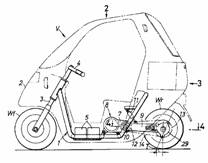
A motorcycle has a frame assembly including a main
frame (5) supporting front (1) and rear (3) wheels on a central line (C0)
thereof, a connecting means (6) mounted on the main frame (5) between the
front (1) and rear (3) wheels, and a subframe (7) mounted on the connecting
means (6) and being capable of banking laterally about the connecting means
(6). At least one of the front (1) and rear (3) wheels is a drive wheel, at
least the drive wheel (3) being capable of preventing the main frame (5) from
banking laterally. Centrifugal forces generated upon cornering are
counterbalanced by centripetal forces produced when only the subframe (7)
banks laterally, and the drive wheel (3) supported on the main frame (5)
which does not bank has an increased road gripping force. Thus,
high-speed cornering is made possbile. |
||||||
|
Patent number |
Title of
the patent |
Publication
date |
Inventor
(s) |
Documents cited by the inventor (s) |
Cited documents in search report |
Other patents where this patent is cited in
search report |
Field of
application |
|
Three-wheeled vehicle |
1987-11-03 |
Shoichiro Irimajiri Takeshi Kawaguchi |
None |
DE402926 |
WO2008079517 FR2818950 US5890558 US5431243 EP0631927 US5236060 |
Miscellaneous |
|
|
Figure |
Abstract |
||||||
|
|
A three-wheeled vehicle has a pair of right and left
wheels provided at either end of the vehicle body and a single wheel provided
at the other end of the vehicle body. The pair of wheels are spaced from each
other laterally with respect to the vehicle body. The three-wheeled vehicle
is further provided with a steering mechanism for steering the pair of
wheels, and a mechanism which cooperates with the steering mechanism for
displacing the single wheel substantially laterally with respect to the
vehicle body and in the direction opposite to the direction of turning of the
vehicle caused by the steering operation of the steering mechanism. In
another embodiment the single wheel is also pivoted in a direction opposite
the turning of the pair of wheels. |
||||||
|
Patent number |
Title of
the patent |
Publication
date |
Inventor
(s) |
Documents cited by the inventor (s) |
Cited documents in search report |
Other patents where this patent is cited in
search report |
Field of
application |
|
Motorcycle sidecar |
1983-05-31 |
Wallace Mitchell |
None |
US1332042 US2702196 US4078815 |
WO2009005250 WO2006088299 US2004026889 US5238258 US5248158 FR2668112 US4477097 |
Miscellaneous |
|
|
Figure |
Abstract |
||||||
|
|
There is disclosed a sidecar having a self-adjusting
castering wheel located forwardly of the rear wheel of the associated
motorcycle and which, together with the sidecar, is connected by a
parallelogram linkage to the frame of the motorcycle so as to lean in
substantial union with the motorcycle and the sidecar body. |
||||||
|
Patent number |
Title of
the patent |
Publication
date |
Inventor
(s) |
Documents cited by the inventor (s) |
Cited documents in search report |
Other patents where this patent is cited in
search report |
Field of
application |
|
Procédé et dispositif
de rotation pour l’équilibration lors du déplacement des véhicules de type
moto-vélo et qui en dérivent |
1977-08-19 |
Marin Paladian |
FR1423736 FR1423965 FR2070627 FR2070971 |
None |
EP1142779 US5927424 WO9534459 WO9406642 US4484648 FR2450480 |
Miscellaneous |
|
|
Figure |
Abstract |
||||||
|
None |
None |
||||||